
Pneumatic Tire

a technology of pneumatic tires and tires, applied in the field of pneumatic tires, can solve problems such as improving wet performance, and achieve the effects of improving snow performance, ensuring the rigidity of the block of land portion 32, and reducing the risk of slipping

Inactive Publication Date: 2017-03-02
THE YOKOHAMA RUBBER CO LTD
View PDF0 Cites 15 Cited by
  • Summary
  • Abstract
  • Description
  • Claims
  • Application Information

AI Technical Summary

Benefits of technology

This technology improves the performance of pneumatic tires in wet or snowy conditions while maintaining their off-road performance. A three-dimensional sipe is created in the center region of the tire tread, which increases the edge component and ensures rigidity while braking or driving on a wet or snowy road. This prevents collapsing of the blocks and improves the tire's off-road performance.

Problems solved by technology

With conventional pneumatic tires mounted to a recreational vehicle (RV), there is a problem of improving a wet performance in addition to an off-road performance (such as a mud performance and a snow performance).

Method used


Image

  • Pneumatic Tire
  • Pneumatic Tire
  • Pneumatic Tire

Examples


modified examples

[0053]FIG. 7 is an explanatory view illustrating a modified example of the pneumatic tire illustrated in FIG. 1. The diagram illustrates an enlarged view of the second land portion 32 having the three-dimensional sipe 52.

[0054]In the configuration of FIG. 4, an inclination angle θ of the three-dimensional sipe 52 relative to the tire circumferential direction is θ=0 degrees. In such a configuration, because the three-dimensional sipe 52 extends in the tire circumferential direction, compared to a configuration where the three-dimensional sipe extends in the tire width direction, a rigidity of the block in the tire circumferential direction is large. By this, collapsing of the block when braking and driving is suppressed and a braking performance of the tire improves.

[0055]However, the present technology is not limited thereto, and as illustrated in FIG. 7, the three-dimensional sipe 52 may be disposed inclined relative to the tire circumferential direction. At this time, the inclina...

examples

[0081]FIG. 9 is a table showing results of performance testing of pneumatic tires according to embodiments of the present technology.

[0082]In this performance testing, evaluations relating to (1) the off-road performance (the snow performance) and (2) the wet performance were performed for a plurality of types of test tires. Additionally, a test tire of a tire size of 265 / 70R17 113T is assembled to a rim of a rim size of 17×7.5J, and an air pressure of 230 kPa and a maximum load of the JATMA standard are imparted to this test tire. Additionally, the test tire is mounted to all wheels of an RV that is a test vehicle.

[0083](1) In the evaluation relating to the off-road performance, the test vehicle travels a test course of a snowy road surface, and a professional test driver makes a sensory evaluation concerning a braking performance and a driving performance. Index evaluation was performed taking the results of the Conventional Example as a reference (100). Larger numerical values ar...


PUM


Abstract

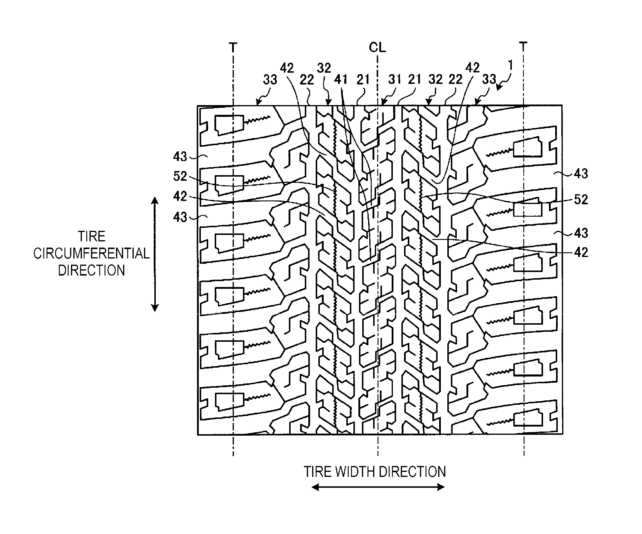
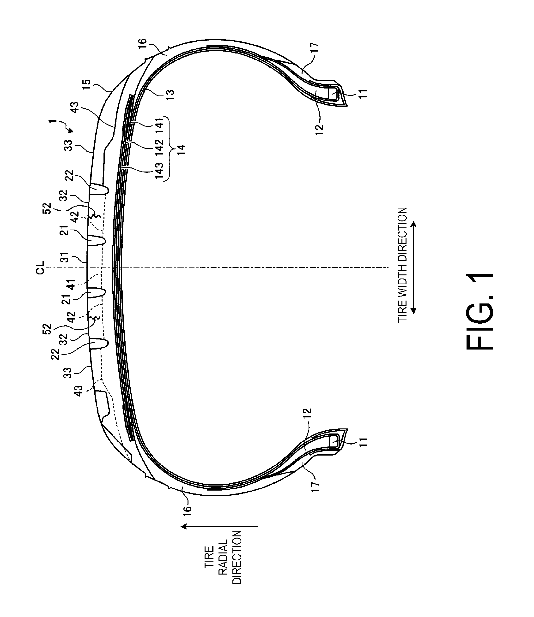
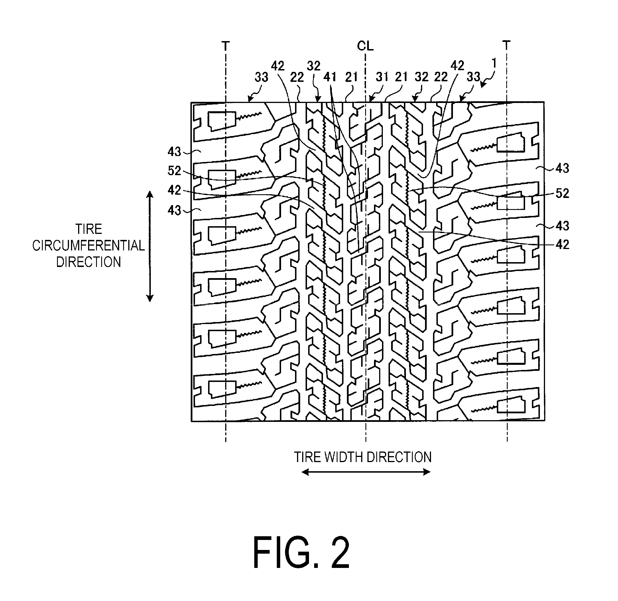
This pneumatic tire (1) is provided with a plurality of circumferential main grooves (21, 22) extending in a tire circumferential direction, a plurality of land portions (31 to 33) defined by these circumferential main grooves (21, 22), and a plurality of lug grooves (41 to 43) disposed in these land portions (31 to 33). Additionally, at least one column of land portion (32) in a tread portion center region is provided with a plurality of blocks divided in the tire circumferential direction by the plurality of lug grooves (42) and a three-dimensional sipe (52) that extends over an entire circumference of the tire and divides the land portion (42) in a tire width direction.

Description

TECHNICAL FIELD[0001]This technology relates to a pneumatic tire and particularly relates to a pneumatic tire capable of improved wet performance while maintaining off-road performance of the tire.BACKGROUND ART[0002]With conventional pneumatic tires mounted to a recreational vehicle (RV), there is a problem of improving a wet performance in addition to an off-road performance (such as a mud performance and a snow performance). Note that as a conventional pneumatic tire having an off-road performance, the technology described in Japanese Patent No. 4350103B is known.SUMMARY[0003]This technology provides a pneumatic tire capable of improved wet performance while maintaining an off-road performance of the tire.[0004]A pneumatic tire according to this technology is a pneumatic tire, provided with: a plurality of circumferential main grooves extending in a tire circumferential direction, a plurality of land portions defined by the circumferential main grooves, and a plurality of lug gro...

Claims


Application Information

Patent Timeline
Patent Type & Authority Applications(United States)
IPC IPC(8): B60C11/12
CPCB60C11/1218B60C11/124B60C2011/1213B60C11/1263B60C11/1236B60C11/0306B60C2011/0346B60C2011/0365B60C2011/0372B60C11/03B60C11/12
Inventor TAKEMORI, RYOHEI
Owner THE YOKOHAMA RUBBER CO LTD
Learn More