
Methods of controlling drill bit trajectory by predicting bit walk and wellbore spiraling

a drill bit and trajectory prediction technology, applied in the direction of survey, instruments, borehole/well accessories, etc., can solve the problems of complex directional drilling process

Active Publication Date: 2017-03-02
BAKER HUGHES INC
View PDF4 Cites 35 Cited by
  • Summary
  • Abstract
  • Description
  • Claims
  • Application Information

AI Technical Summary

Benefits of technology

The patent text describes a method for predicting the path of a drill bit in a subterranean formation using a computer model of the drill bit and the formation. The model takes into account various parameters such as the dimensions and geometry of the drill bit and the borehole, the weight-on-bit, and the material properties of the formation. The method can be used to control the drill bit trajectory to avoid wellbore spiraling or bit walk, and can also be used to plan and drill a wellbore in a specific formation. The technical effects of this method include improved wellbore trajectory control and reduced wellbore drilling time and cost.

Problems solved by technology

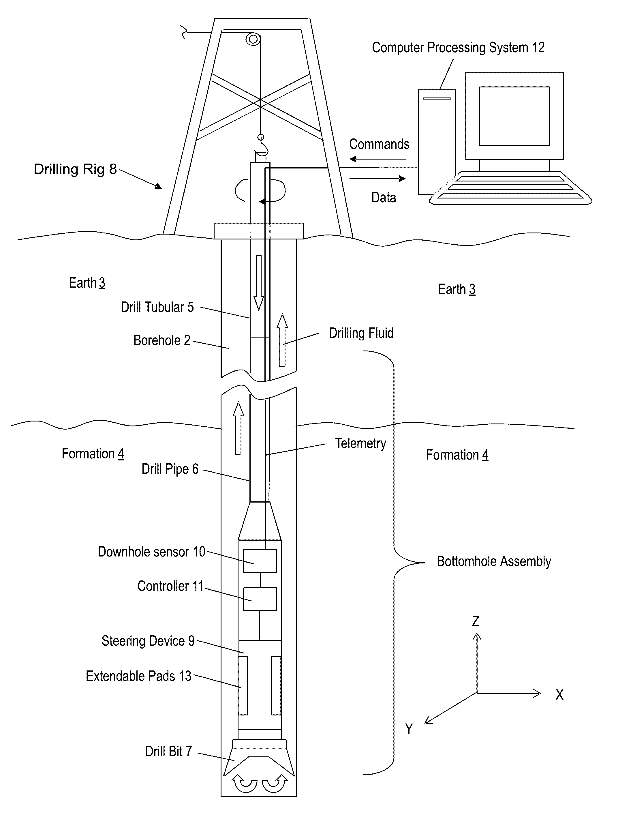
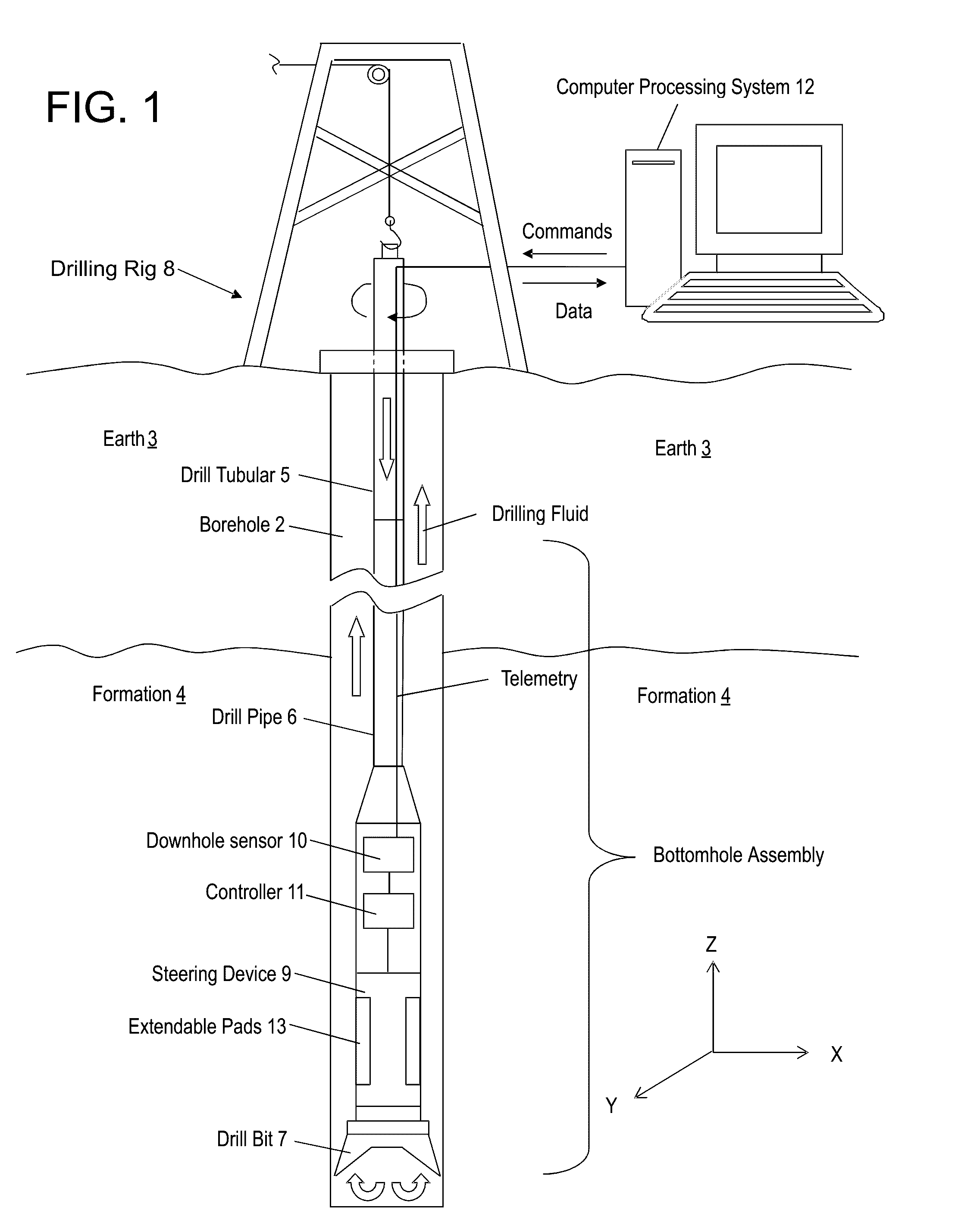
The processes of directional drilling are complicated by the complex interaction of forces between the drill bit and the walls of the subterranean formation lining the well borehole.

Method used


Image

  • Methods of controlling drill bit trajectory by predicting bit walk and wellbore spiraling
  • Methods of controlling drill bit trajectory by predicting bit walk and wellbore spiraling
  • Methods of controlling drill bit trajectory by predicting bit walk and wellbore spiraling

Examples


embodiment 1

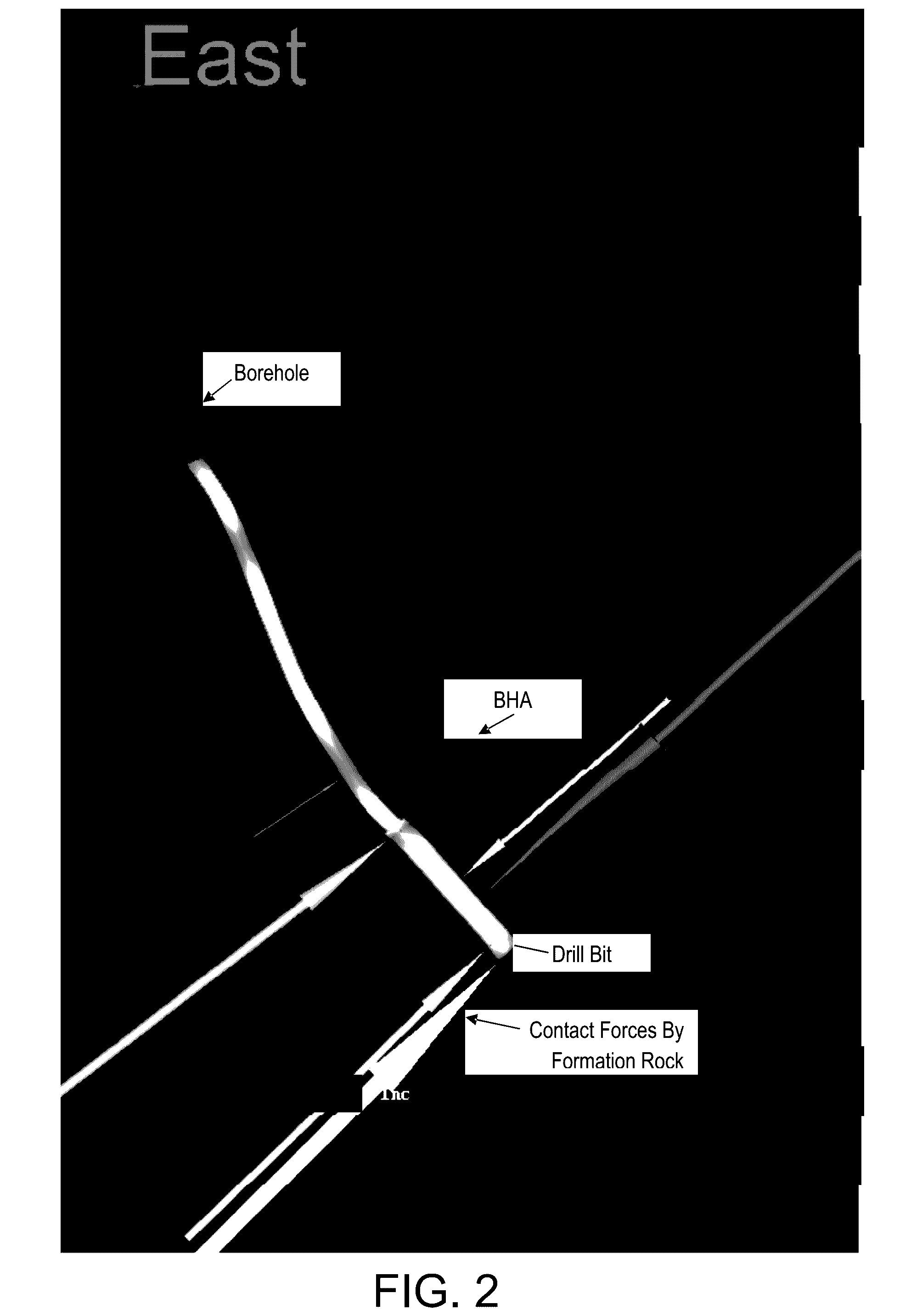
[0179]A method of controlling drill bit trajectory in a subterranean formation, the method comprising: receiving drilling parameters for operating a specific bottomhole assembly (BHA); constructing, with a computer processor, a directional drill-ahead simulator comprising a computer model of the BHA and the subterranean formation; calculating, with the computer processor, axial motion and lateral motion of a drill bit connected to a bottom end of the BHA using at least one formation parameter and at least one drilling parameter; predicting, with the computer processor, bit walk of the drill bit by accounting for and calculating contact forces and frictional forces between the BHA and a wall of a borehole in the subterranean formation using the computer model of the BHA; determining, with the computer processor, an adjusted drill bit trajectory to account for the predicted bit walk; determining adjusted drilling parameters for operating the BHA to substantially follow the adjusted dr...

embodiment 2

[0180]The method of Embodiment 1, further comprising predicting wellbore spiraling by accounting for and calculating the contact forces and the frictional forces using the computer model of the BHA.

embodiment 3

[0181]The method of Embodiment 1, wherein constructing the directional drill-ahead simulator comprising the BHA computer model comprises: constructing a three-dimensional model of the BHA and the subterranean formation; configuring the BHA computer model to be a dynamic model in a depth domain; configuring the BHA computer model to predict a build-up-rate based at least in part on the predicted bit walk of the drill bit using error-reducing iterations in each step of a finite element analysis; and configuring the BHA computer model to operate in real time during drilling operations.


PUM


Abstract

A method of controlling drill bit trajectory in a subterranean formation includes receiving drilling parameters for operating a specific bottomhole assembly (BHA), constructing, with a computer processor, a directional drill-ahead simulator including a computer model of the BHA and the subterranean formation, calculating axial motion and lateral motion of a drill bit connected to a bottom end of the BHA using formation parameters and drilling parameters, predicting bit walk of the drill bit by accounting for and calculating contact forces and frictional forces between the BHA and a wall of a borehole in the subterranean formation using the computer model of the BHA, and determining an adjusted drill bit trajectory to account for the predicted bit walk. The method includes determining adjusted drilling parameters for operating the BHA to substantially follow the adjusted drill bit trajectory and operating the BHA according to the adjusted drilling parameters.

Description

CROSS-REFERENCE TO RELATED APPLICATIONS[0001]This application is a continuation-in-part application of U.S. patent application Ser. No. 14 / 517,433, filed Oct. 17, 2014, titled “DIRECTIONAL DRILL AHEAD SIMULATOR: DIRECTIONAL WELLBORE PREDICTION USING BHA AND BIT MODELS,” which claims the benefit of U.S. Provisional Patent Application Ser. No. 61 / 892,959, filed Oct. 18, 2013, and this application also claims the benefit of U.S. Provisional Patent Application Ser. No. 62 / 364,833, filed Jul. 20, 2016, the disclosure of each of which is incorporated herein in its entirety by this reference.[0002]The subject matter of this application is also related to the subject matter of U.S. patent application Ser. No. 14 / 517,445, filed Oct. 17, 2014, titled “AXIAL MOTION DRILL BIT MODEL,” which claims the benefit of U.S. Provisional Patent Application Ser. No. 61 / 892,992, filed Oct. 18, 2013, and the subject matter of this application is also related to the subject matter of U.S. patent application ...

Claims


Application Information

Patent Timeline
Patent Type & Authority Applications(United States)
IPC IPC(8): E21B44/02E21B44/06G06F17/50E21B41/00E21B45/00E21B47/12E21B44/04E21B7/06
CPCE21B44/02E21B44/04E21B44/06E21B7/06E21B41/0092G06F2217/16E21B47/12G06F17/5004G06F17/5009G06F2217/34E21B45/00E21B7/04G06F30/13G06F30/20G06F2111/10G06F2113/14Y02C20/40
Inventor SPENCER, REED W.UNO, TIMOTHY P.HANSON, JONATHAN M.
Owner BAKER HUGHES INC
Learn More