

Lighting device and display device
a technology of light source and display device, which is applied in the direction of planar/plate-like light guide, transportation and packaging, instruments, etc., can solve the problems of likely cause of warping or wrinkles, and achieve the effect of uneven brightness
- Summary
- Abstract
- Description
- Claims
- Application Information
AI Technical Summary
Benefits of technology
Problems solved by technology
Method used
Image

Examples
first embodiment
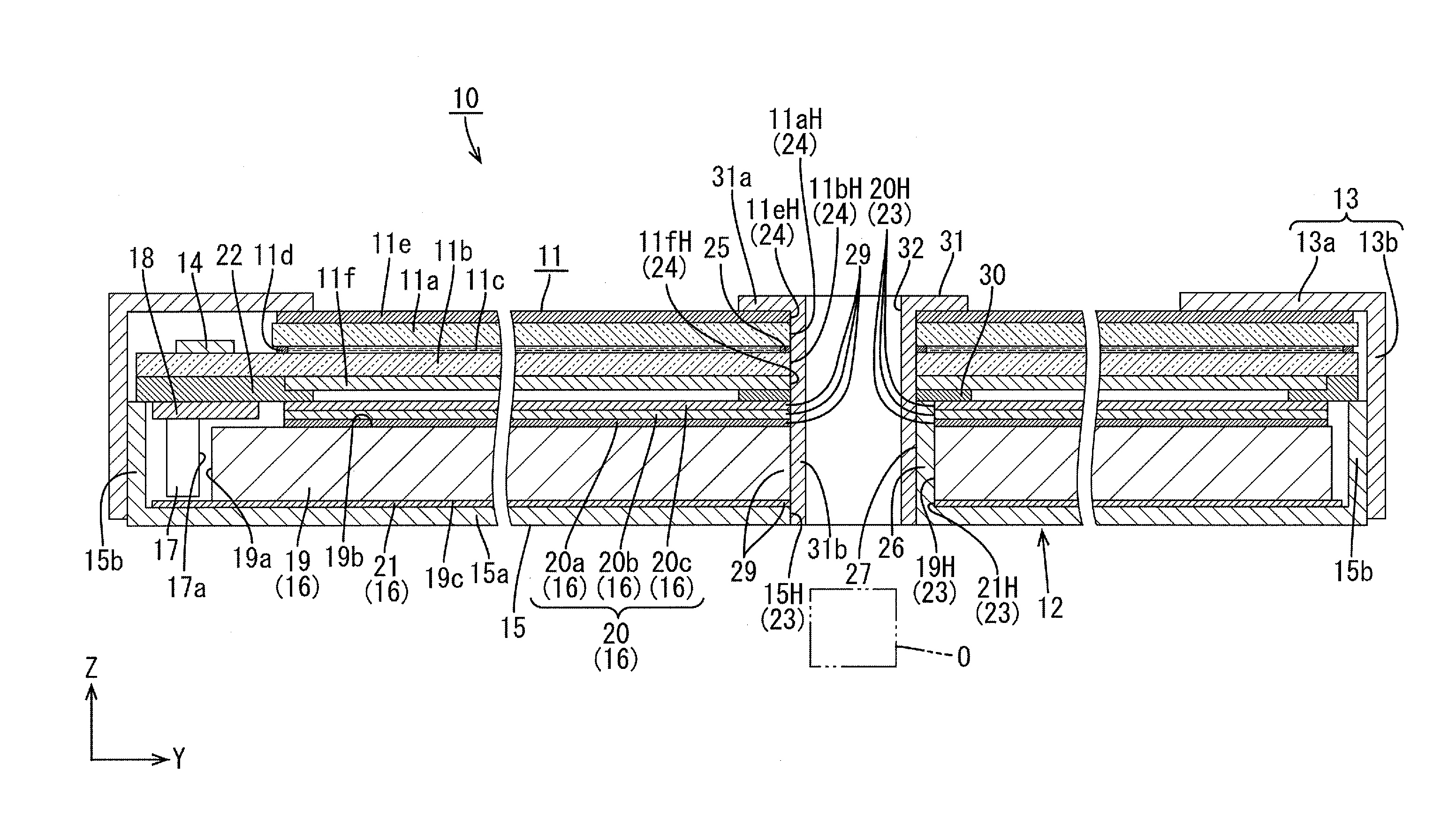
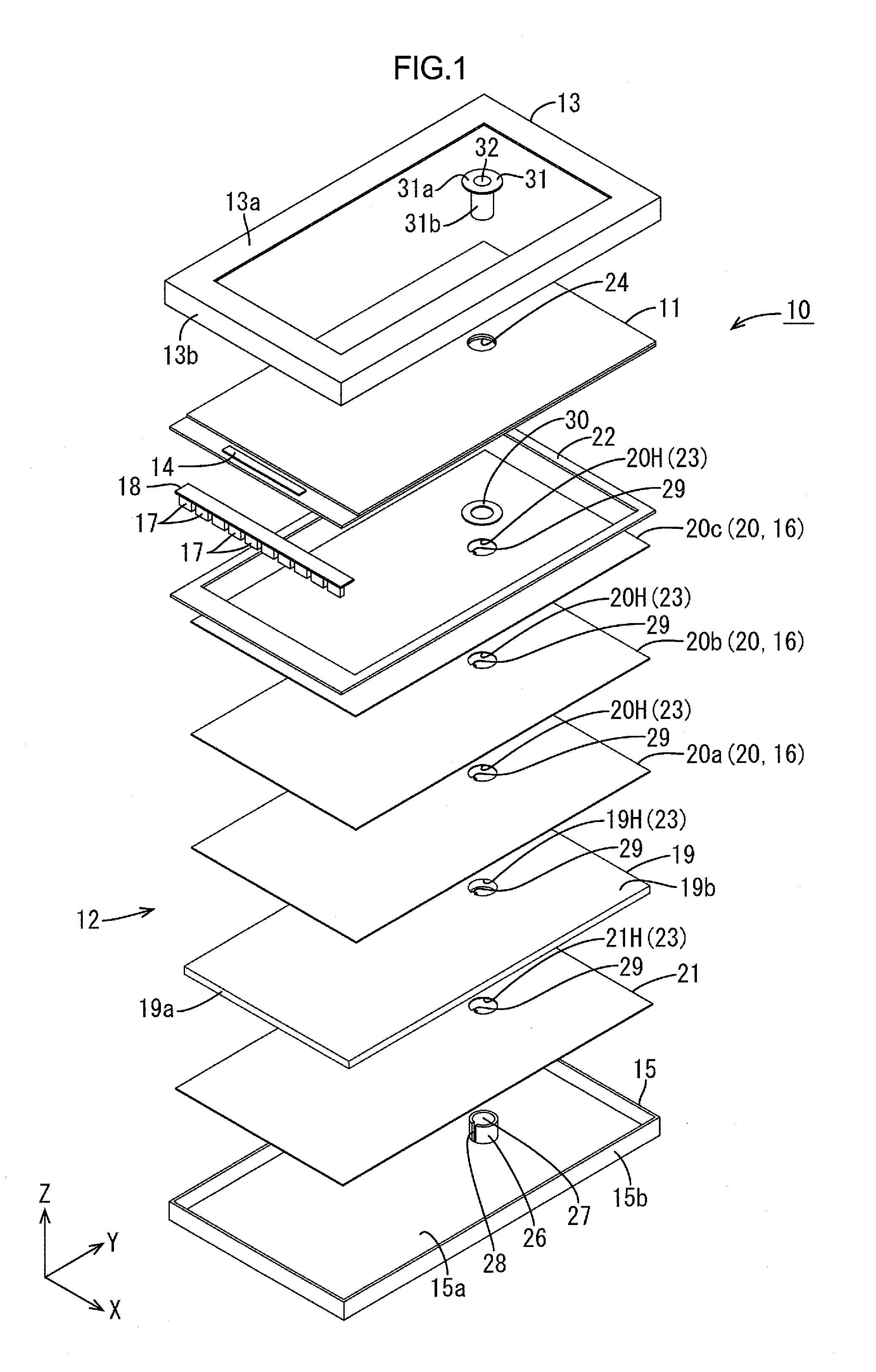
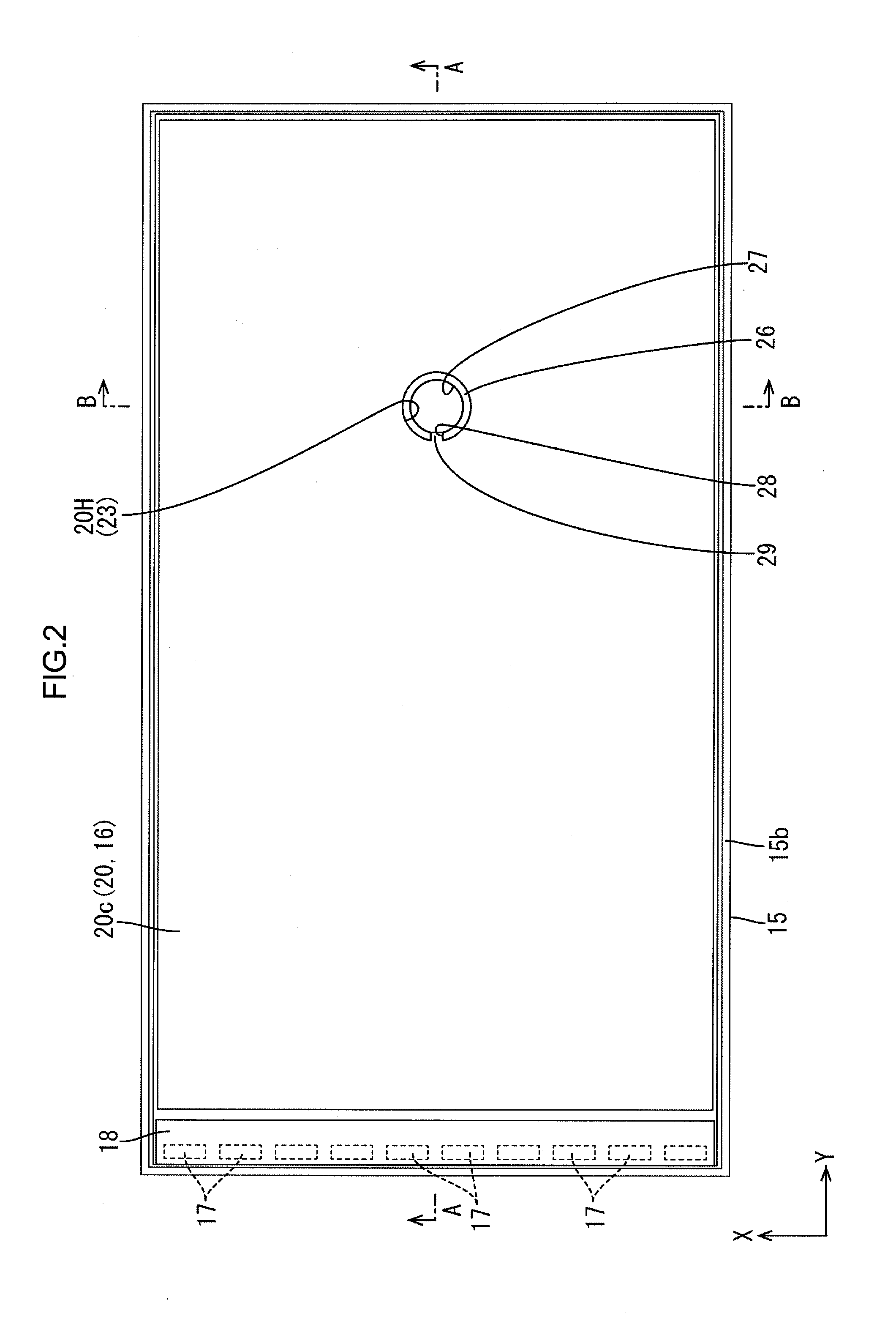
[0076]A first embodiment of the present technology will be described with reference to FIGS. 1 to 5. In this embodiment, a liquid crystal display device (a display device) 10 including a liquid crystal panel 11 as a display panel will be described. X-axis, Y-axis and Z-axis may be indicated in some of the drawings. The axes in each drawing correspond to the respective axes in other drawings. An upper-lower direction is referred with reference to FIGS. 3 and 4, and an upper side is a front-surface side and a lower side is a rear-surface side in FIGS. 3 and 4.
[0077]As illustrated in FIG. 1, the liquid crystal display device 10 has a rectangular overall shape. The liquid crystal display device 10 includes a liquid crystal panel (a display panel) 11 for displaying images thereon, a backlight device (a lighting device) 12 on the rear-surface side with respect to the liquid crystal panel 11) for providing light toward the liquid crystal panel 11 for displaying, and a bezel (an outer perip...
second embodiment
[0115]A second embodiment of the present technology will be described with reference to FIGS. 6 and 7. In the second embodiment, multiple members included in an optical member 116 selectively have an optical member-side projection portion 129. Similar configurations, operations, and effects to the first embodiment will not be described.
[0116]Each of optical sheets 120 included in the optical member 116 of the present embodiment (a diffuser sheet 120a, a first prism sheet 120b, and a second prism sheet 120c) has an optical member-side projection portion 129, selectively, as illustrated in FIGS. 6 and 7. Namely, a light guide plate 119 and a reflection sheet 121 do not have the optical member-side projection portion 129 and only the optical sheets 120 have the optical member-side projection portion 129. The light guide plate 119 has a light guide plate-side through hole 119H and the reflection sheet 121 has a reflection sheet-side through hole 121H and the through holes 119H, 121H for...
third embodiment
[0121]A third embodiment of the present technology will be described with reference to FIGS. 8 and 9. The third embodiment further includes a positioning structure in an optical sheet 220 and a restricting member 226 unlike the second embodiment. Similar configurations, operations, and effects to the second embodiment will not be described.
[0122]As illustrated in FIGS. 8 and 9, the restricting member 226 of the present embodiment includes a positioning pin 34 and an optical member-side projection portion 229 of each optical sheet 220 includes a positioning hole 35 where the positioning pin 34 is inserted. The positioning pin 34 projects from a bottom surface of a restricting member-side recessed portion 229 of the restricting member 226 toward the front-surface side in the Z-axis direction (the thickness direction of an optical member 216). The positioning pin 34 has a post-like shape and is disposed substantially at a center of the bottom surface of the restricting member-side rece...
PUM
| Property | Measurement | Unit |
|---|---|---|
| angle | aaaaa | aaaaa |
| angle | aaaaa | aaaaa |
| thickness | aaaaa | aaaaa |
Abstract
Description
Claims
Application Information