Transparent display device

Active Publication Date: 2017-03-02
LG DISPLAY CO LTD
View PDF22 Cites 21 Cited by
  • Summary
  • Abstract
  • Description
  • Claims
  • Application Information

AI Technical Summary

Benefits of technology

[0016]Further, in the transparent display device according to the present disclosure, all of circuits required for the display device are disposed in a circuit region disposed under the transmissive region and the emission region. Thus, an opaque circuit region can be minimized.
[0017]Furthermore, the transparent display device according to the present disclosure does not include a reflective plate. Thus, a co

Problems solved by technology

In a transparent display device using a reflective plate, if a panel design is changed to increase transparency, an emission area may become, however, decreased and thus, the emission efficiency ma

Method used


Image

  • Transparent display device
  • Transparent display device
  • Transparent display device

Examples


Example

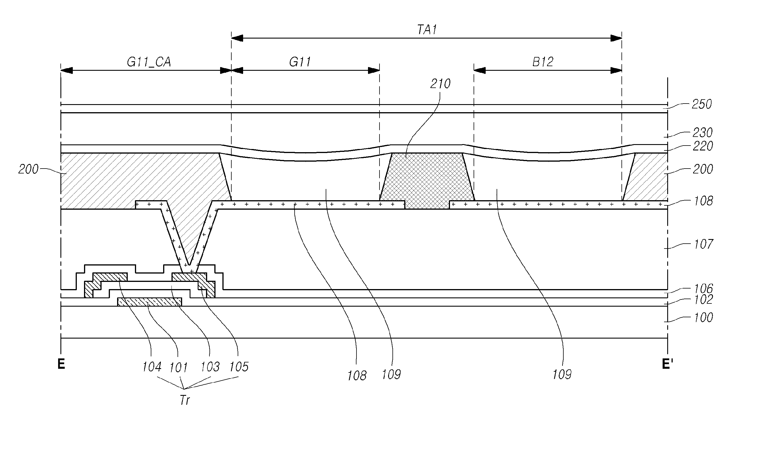
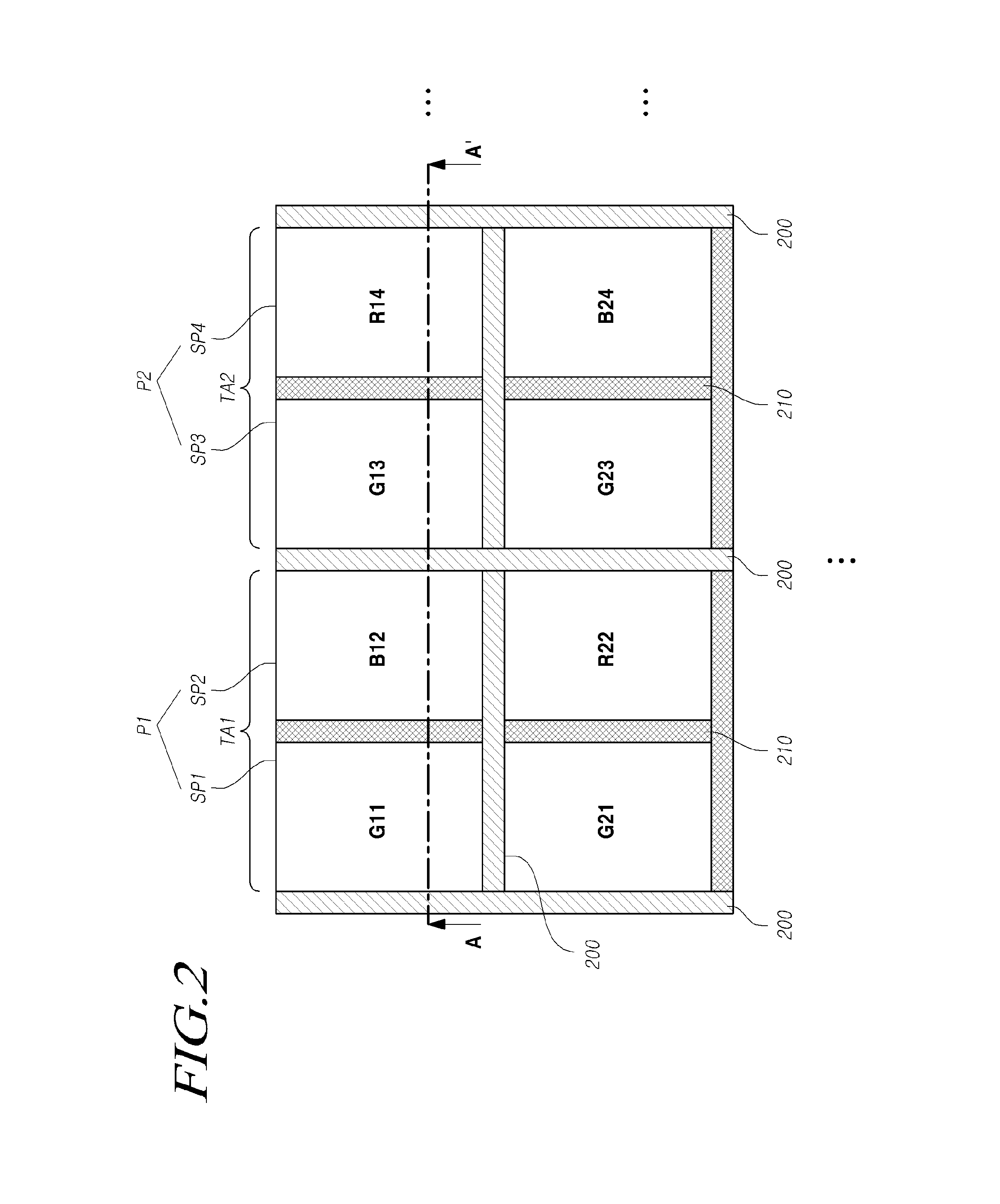
[0081]Hereinafter, a transparent display device according to a second exemplary embodiment of the present disclosure will be described with reference to FIG. 4 and FIG. 5. FIG. 4 is a plane view of a transparent display device according to the second exemplary embodiment of the present disclosure. FIG. 5 is a cross-sectional view taken along line B-B′ of the transparent display device according to the second exemplary embodiment of the present disclosure. The transparent display device according to the second exemplary embodiment may include the same components as those of the first exemplary embodiment. The redundant description thereof may be omitted herein for conciseness. Further, like components are assigned like reference numerals.

[0082]Referring to FIG. 4 and FIG. 5, two sub-pixel regions may constitute one pixel region. For example, a first sub-pixel region SP1 and a second sub-pixel region SP2 may constitute a first pixel region P1.

[0083]Further, one pixel region may includ...

Example

[0089]Hereinafter, a transparent display device according to a third exemplary embodiment of the present disclosure will be described with reference to FIG. 6 and FIG. 7. FIG. 6 is a plane view of the transparent display device according to the third exemplary embodiment of the present disclosure. FIG. 7 is a cross-sectional view taken along line C-C′ of the transparent display device according to the third exemplary embodiment of the present disclosure. The transparent display device according to the third exemplary embodiment may include the same components as those of the above-described exemplary embodiments. The redundant description thereof may be omitted herein. Further, like components are assigned like reference numerals.

[0090]Referring to FIG. 6 and FIG. 7, in the transparent display device according to the third exemplary embodiment of the present disclosure, one pixel region may include one transmissive region, and the one transmissive region may include two emission reg...


PUM


Abstract

Disclosed is a transparent display device that includes a plurality of column lines and a plurality of horizontal lines crossing each other to define a plurality of pixel regions in a matrix, each column line including at least two data lines and a voltage line, and each horizontal line including a gate line; a first transparent electrode in each emission region; a transparent organic light emitting layer on the first electrode; and a second transparent electrode on the organic light emitting layer, wherein each pixel region includes a transmissive region and a circuit region, and wherein the transmissive region includes at least two emission regions that are divided by a first transparent bank pattern.

Description

CROSS-REFERENCE TO RELATED APPLICATIONS[0001]This application claims priority to and benefit from Korean Patent Application No. 2015-0118766 filed on Aug. 24, 2015.BACKGROUND[0002]Field of Disclosure[0003]The present disclosure relates to a transparent display device and a method of manufacturing the same.[0004]Description of the Related Art[0005]With progress to the information-oriented society, various demands for display devices for displaying an image are increasing. Recently, various kinds of display devices such as a liquid crystal display device, a plasma transparent display panel device, and an organic light emitting display device have been used.[0006]Further, in recent years, display devices have been actively developed. Accordingly, display devices, which have various designs differentiated from a conventional design with an improved aesthetic function and user functions, have been discussed. For example, a transparent display device has been suggested.[0007]In order to i...

Claims


Application Information

Patent Timeline
IPC IPC(8): H01L27/32H01L51/52
CPCH01L27/3246H01L51/5284H01L27/3216H01L2251/5323H01L27/3218H01L27/3276H01L51/5234H10K59/121H10K59/122H10K50/865H10K2102/3031H10K50/828H10K59/131H10K59/352H10K59/353
Inventor KIM, EUITAECHO, NAMWOOKKIM, HYOUNG-SUYOON, DOOHYUN
Owner LG DISPLAY CO LTD
Why Eureka
Try Eureka