
Compact wideband dual polarized dipole

Inactive Publication Date: 2017-03-02
AMPHENOL CORP
View PDF4 Cites 47 Cited by
  • Summary
  • Abstract
  • Description
  • Claims
  • Application Information

AI Technical Summary

Benefits of technology

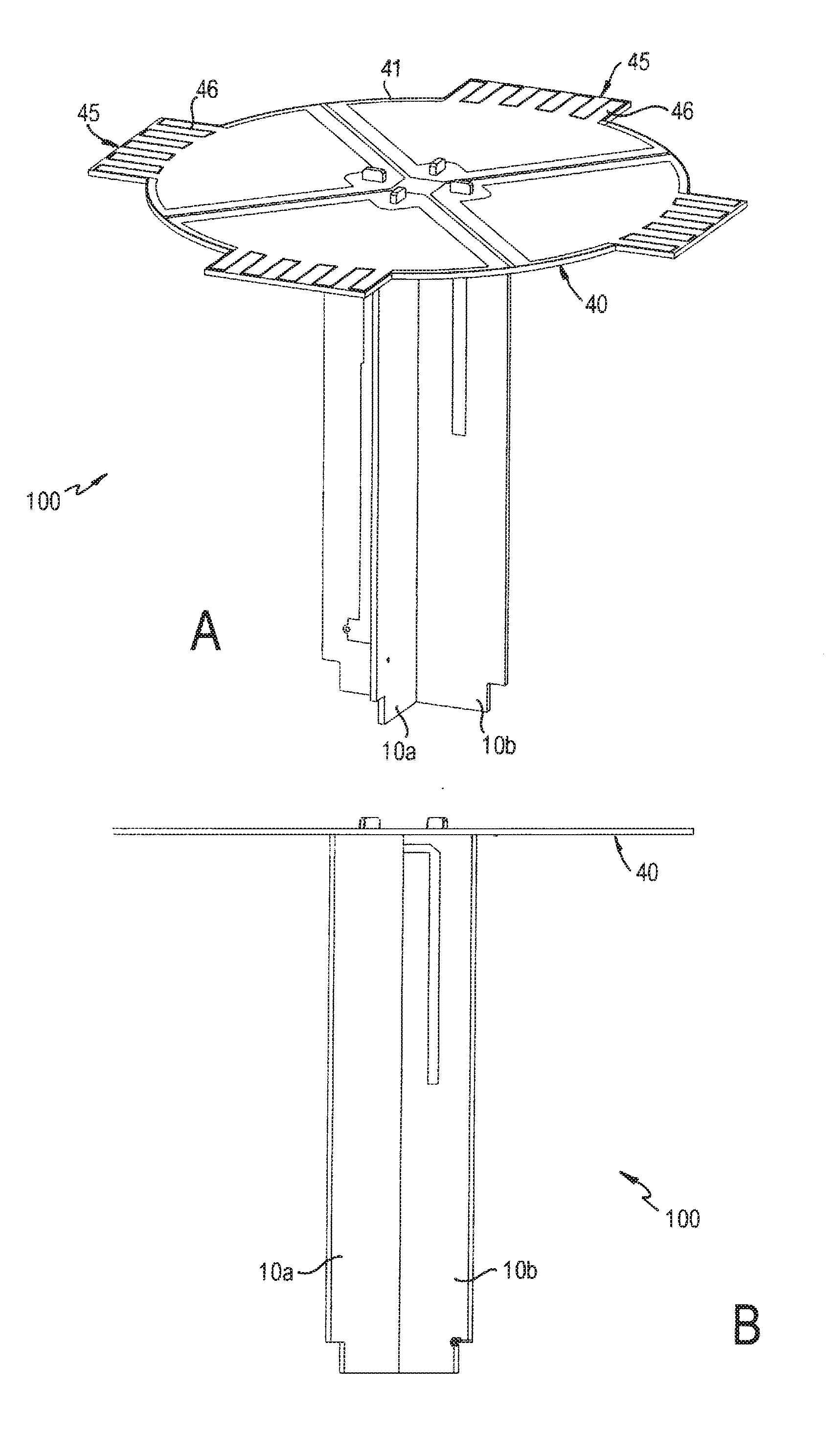
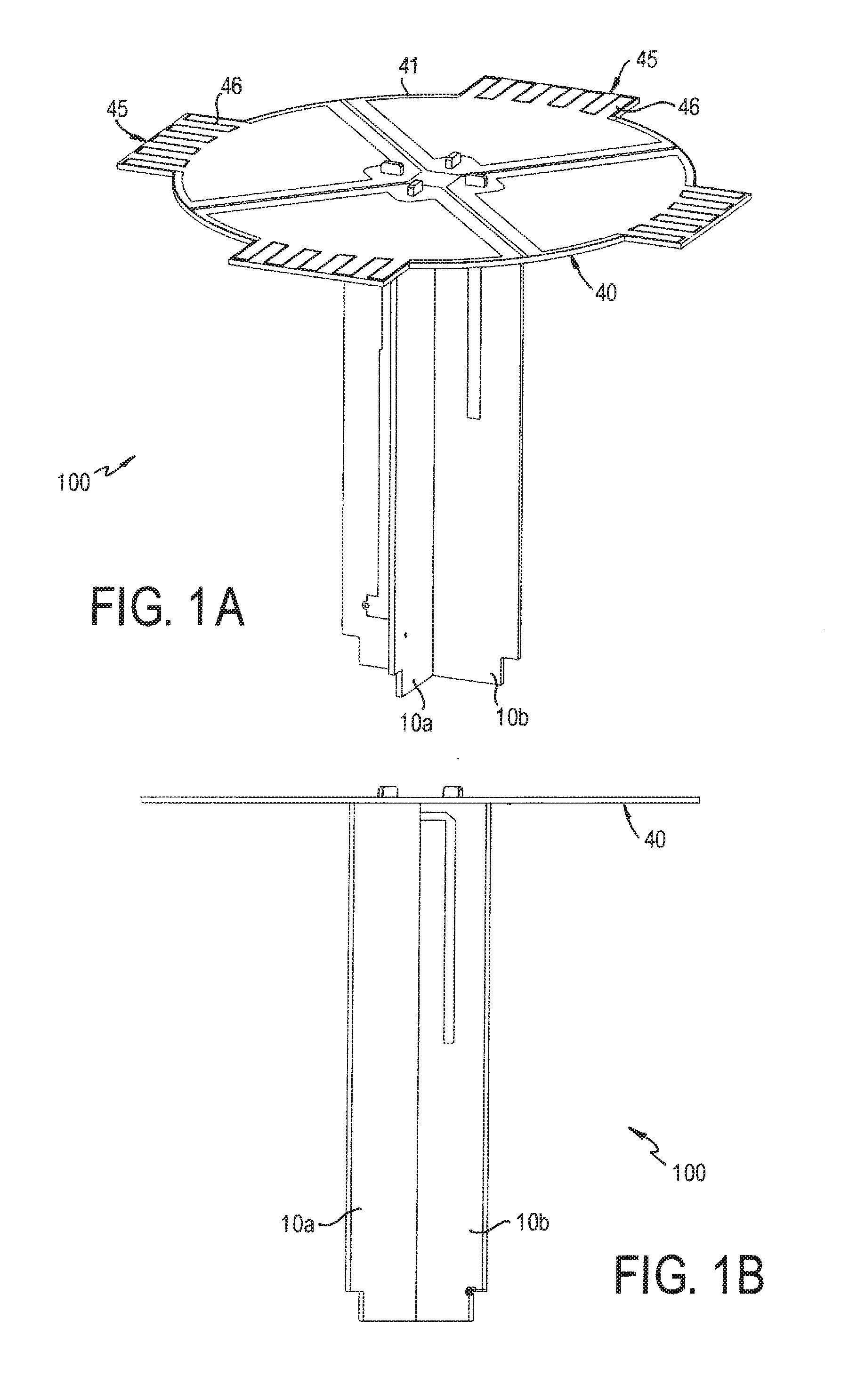
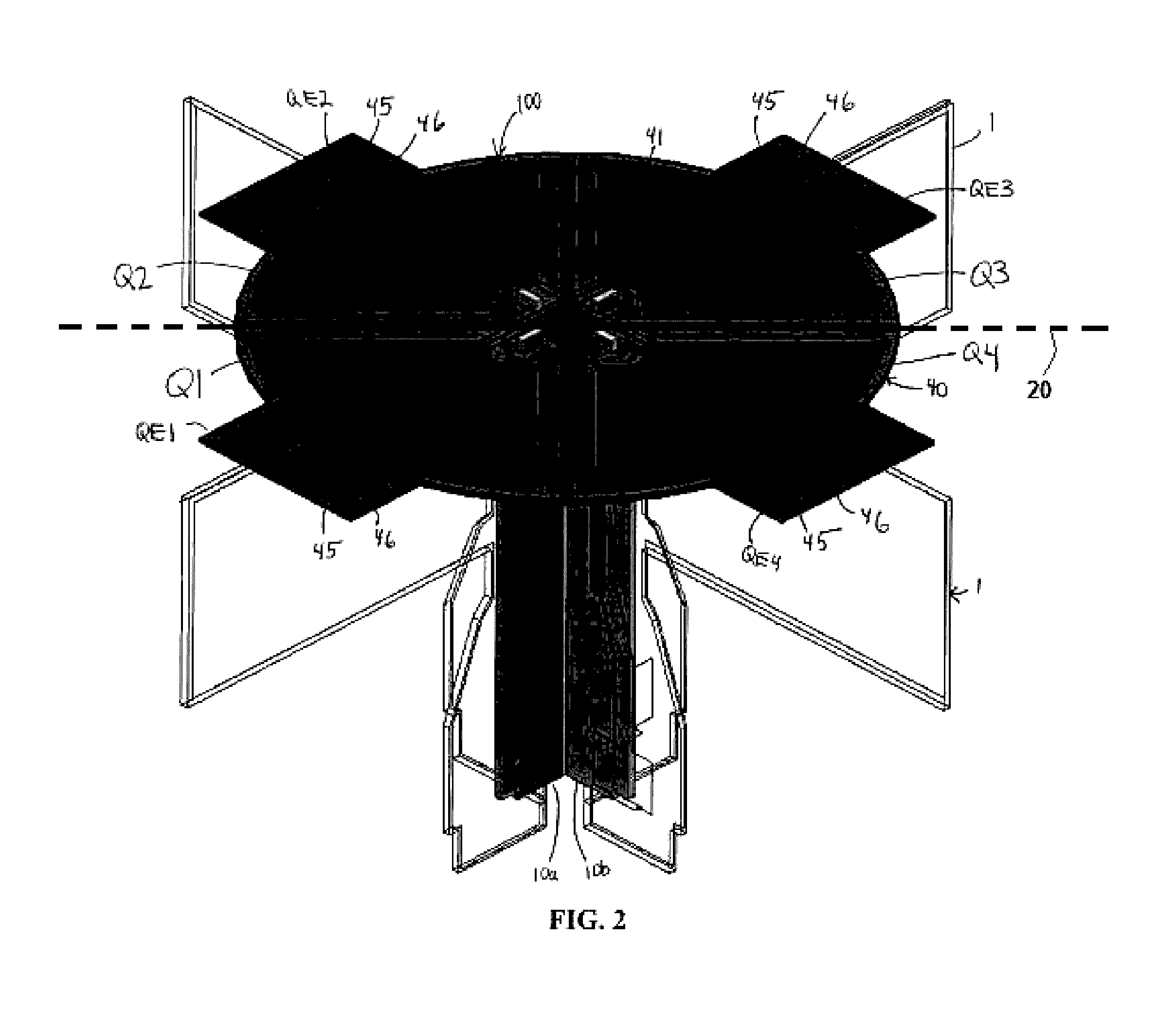
The patent describes a dual-polarized dipole antenna assembly that includes a first balun, a second balun, and a radiating printed circuit board. The printed circuit board is positioned perpendicular to the baluns and has meander line components associated with both polarizations. The PCB has first and third quadrants for the first polarization and second and fourth quadrants for the second polarization, which are sector-shaped and have radially extended portions that include the meander line components. The conductors of the meander line components are positioned on a single surface of the substrate. The first balun and second balun are arranged in a ±45° configuration, producing two orthogonal polarization states. The antenna assembly is scalable and operates at various frequency bands.

Problems solved by technology

Current antenna structures of, for example, Tri band configurations have to provide some level of performance compromise due to the number of bands which result in asymmetry in horizontal pattern shaping.
The larger operating bandwidths have resulted in more compromised performance over the bands of operation that increases both the distortion (azimuth tracking) and cross-polarization discrimination ratio (XPD).
The current pattern distortion results in coverage hand-off issues and planning concerns for wireless operators through a parameter of azimuth tracking which can be in excess of 5 dB.

Method used


Image

  • Compact wideband dual polarized dipole
  • Compact wideband dual polarized dipole
  • Compact wideband dual polarized dipole

Examples


Embodiment Construction

[0033]It is to be understood that the figures and descriptions of the present invention may have been simplified to illustrate elements that are relevant for a clear understanding of the present invention, while eliminating, for purposes of clarity, other elements found in a typical dipole antenna assembly. Those of ordinary skill in the art will recognize that other elements may be desirable and / or required in order to implement the present invention. However, because such elements are well known in the art, and because they do not facilitate a better understanding of the present invention, a discussion of such elements is not provided herein. It is also to be understood that the drawings included herewith only provide diagrammatic representations of the presently preferred structures of the present invention and that structures falling within the scope of the present invention may include structures different than those shown in the drawings. Reference will now be made to the draw...


PUM


Abstract

A compact wideband dual polarized dipole antenna assembly using a meander line component. The antenna assembly includes a pair of open stub baluns with a radiating dual polarized top printed circuit board (PCB) that is perpendicular to the baluns. The radiating dual polarized top PCB includes the meander line component. The compact dipole solution, through the use of the meander line component, may be employed in more complex multi-band products resulting in a reduction in metal required and does not compromise in performance during multi-band operation. The compact wideband dual polarized dipole antenna assembly covers all known radio frequency bands in, for example, the mobile base station industry to date.

Description

CROSS REFERENCE TO RELATED APPLICATION(S)[0001]This application claims priority from U.S. Provisional Patent Application. No. 62 / 211,033, filed on Aug. 28, 2015, which is hereby incorporated herein by reference in its entirety.FIELD OF THE INVENTION[0002]Embodiments are in the field of dipole antennas. More particularly, embodiments disclosed herein relate to compact wideband dual polarized dipole antenna assemblies which, inter alia, foster a compact dipole solution through the use of a meander line component that may be employed in more complex multi-band products and that does not compromise in performance during multi-band operation.BACKGROUND OF THE INVENTION[0003]The mobile base station industry is becoming increasingly more competitive. As new frequency bands are being made available, it is a goal of those involved in the design and use of mobile base station antennas and other related systems to maintain or reduce costs, while maintaining or improving upon electrical perform...

Claims


Application Information

Patent Timeline
IPC IPC(8): H01Q9/44H01Q21/24H01Q1/38H01Q5/50
CPCH01Q9/44H01Q1/38H01Q21/24H01Q5/50H01Q1/246H01Q9/28
Inventor CAO, TAN HUY
Owner AMPHENOL CORP
Learn More