Overcurrent Protective Device, Electronic Apparatus, Integrated Circuit, and Signal Transmission Circuit

a technology of overcurrent protection and protective device, which is applied in the direction of emergency protective arrangement for limiting excess voltage/current, electronic switching, and pulse technique, etc. it can solve the problems of insufficient maintenance, inability to perform timely overcurrent protection operation, and inability to substantially apply voltage to a control circuit. , to achieve the effect of suppressing an increase in the circuit scale of the control circuit, protecting the electronic apparatus, and reducing the substantially applied voltage to the control circui

Active Publication Date: 2017-03-02
ROHM CO LTD
View PDF5 Cites 30 Cited by
  • Summary
  • Abstract
  • Description
  • Claims
  • Application Information

AI Technical Summary

Benefits of technology

[0020]An object of a third aspect of the present invention is to provide a circuit which suppresses passage of a current in an electronic apparatus and thus protects the electronic apparatus even when in the electronic apparatus an internal circuit short-circuits and fails.
[0037]According to the fifth or sixth aspect of the present invention, a signal transmission circuit and overcurrent protective device can be provided which can prevent an erroneous operation of a load by maintaining, at a low voltage, erroneous signal transmission caused as a high temperature leakage current, a noise, etc. are generated, while reducing power consumption.

Problems solved by technology

However, the fuse interrupts an overcurrent by being blown itself, and accordingly, once the fuse has interrupted an overcurrent, the fuse must be replaced with another, and is thus not maintenance-free.
When the delay time until the overcurrent protective operation is performed is constant, there is a possibility that the overcurrent protective operation may not be performed timely in response to the magnitude of the overcurrent.
For example, when the overcurrent has a large magnitude, the overcurrent protective operation may not be performed even though a time to perform the overcurrent protective operation has passed.
Reversely, when the overcurrent has a small magnitude, an unnecessary overcurrent protective operation may be performed even though a time to perform the overcurrent protective operation has not arrived.

Method used


Image

  • Overcurrent Protective Device, Electronic Apparatus, Integrated Circuit, and Signal Transmission Circuit
  • Overcurrent Protective Device, Electronic Apparatus, Integrated Circuit, and Signal Transmission Circuit
  • Overcurrent Protective Device, Electronic Apparatus, Integrated Circuit, and Signal Transmission Circuit

Examples


first embodiment

in Exemplary Variation

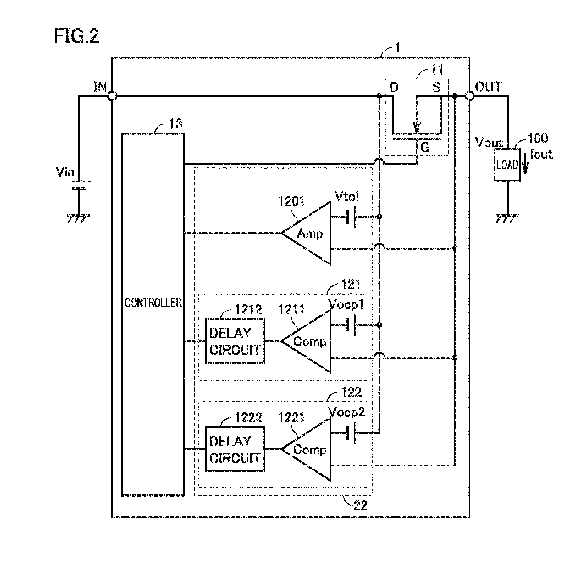
[0104]In the first embodiment, a case where detector 22 includes two detection circuits is illustrated. The number of the detection circuits which detector 22 includes is not limited to two. An exemplary variation of the first embodiment illustrates a case where detector 22 includes three or more detection circuits.

[0105]The exemplary variation of the first embodiment is different from the first embodiment in that the detector includes N detection circuits, where N>2. The remainder in configuration is similar to that of the first embodiment, and accordingly, it will not be described repeatedly.

[0106]FIG. 6 is a functional block diagram for illustrating a function of an overcurrent protective device 1A according to the exemplary variation of the first embodiment. As shown in FIG. 6, detector 22A includes a first detection circuit, a second detection circuit, . . . and an Nth detection circuit. Each detecting circuit includes a comparator and a delay circuit in a...

second embodiment

[0114]In the first embodiment a configuration is described in which once controller 13 has turned off FET 11, thereafter controller 13 does not return FET 11 to an electrical conduction state automatically. In the second embodiment a case will be described in which after controller 13 turns off FET 11 once a prescribed period of time elapses controller 13 returns FET 11 to the electrical conduction state.

[0115]The second embodiment is different from the first embodiment in that after controller 13 turns off FET 11 once a prescribed period of time elapses controller 13 returns FET 11 to the electrical conduction state. The remainder in configuration is similar to that of the first embodiment, and accordingly, it will not be described repeatedly.

[0116]FIG. 10 is a time chart of current Tout in the second embodiment. As shown in FIG. 10, current Tout between time t11 and time t12 exceeds first threshold value Iocp1. The period of time from time t11 to time t12 reaches first delay time ...

third embodiment

[0120]In the first embodiment a configuration is described in which detector 22 includes a plurality of detection circuits with different delay times to implement a delay time corresponding to a magnitude of current Tout. The method of implementing a delay time depending on a magnitude of current Tout is not limited to the method using the plurality of detection circuits with different delay times. In a third embodiment a case will be described in which a delay time is dynamically varied depending on current Tout.

[0121]The third embodiment is different from the first embodiment in that an overcurrent protective device according to the third embodiment includes an adjustment unit which varies a delay time dynamically depending on current Tout. The remainder is similar to that of the first embodiment, and accordingly, it will not be described repeatedly. Note that while FIG. 11 shows only the first detection circuit for the sake of illustration, the detector may include a plurality of...


PUM


Abstract

The present overcurrent protective device comprises an input terminal configured to receive a power supply voltage, an output terminal, a switch, a detector, and a controller. The switch is provided between the input terminal and the output terminal. The detector is configured to output a limitation signal without delay when a current flowing through the switch exceeds a prescribed tolerance value. The controller is configured to receive the limitation signal and control the switch to prevent the current from exceeding the tolerance value. The detector is configured output a turn-off signal to the controller when a first state continues for a delay time determined depending on the current's magnitude. The first state is a state where the current is smaller than the tolerance value and the current exceeds a first threshold value smaller than the tolerance value. The controller turns off the switch in response to the turn-off signal.

Description

BACKGROUND OF THE INVENTION[0001]Field of the Invention[0002]The present invention relates to an overcurrent protective device, an electronic apparatus having the overcurrent protective device mounted therein, an integrated circuit having the overcurrent protective device integrated therewith, and a signal transmission circuit which transmits a signal from an input terminal to an output terminal via a switch or interrupts such a signal, and particularly to a technology for protecting the electronic apparatus when an internal circuit fails and short-circuits, and a signal transmission circuit and an overcurrent protective device which prevent an erroneous operation of a load by maintaining, at a low voltage, erroneous signal transmission caused by a high temperature leakage current, a noise, and the like.[0003]Description of the Background Art[0004]An overcurrent protective device is known which prevents an overcurrent by limiting a current supplied to a load. For example, Japanese P...

Claims


Application Information

Patent Timeline
Patent Type & Authority Applications(United States)
IPC IPC(8): H02H3/10H03K17/687H02H1/00H01L27/02H01L29/866
CPCH02H3/10H01L27/0255H03K17/687H02H1/0007H01L29/866H03K17/0822H03K17/145H02H3/025H02H3/0935H02H9/025H01L27/0285
Inventor YASUSAKA, MAKOTOSHUGO, DAISAKUHIRATA, SHINICHI
Owner ROHM CO LTD
Why Eureka
Try Eureka