Battery module voltage control device, battery module, and power supply system

a battery module and voltage control technology, applied in process and machine control, emergency power supply arrangements, safe/protective circuits, etc., can solve problems such as data loss and system failure, unstable operation, and uninterruptible power supply devices, so as to prevent erroneous load operation and stable voltage

Active Publication Date: 2019-08-13
MURATA MFG CO LTD
View PDF109 Cites 0 Cited by
  • Summary
  • Abstract
  • Description
  • Claims
  • Application Information

AI Technical Summary

Benefits of technology

[0011]With this configuration, in a state where the output current value of the converter unit is equal to or higher than the first threshold and the converter unit performs constant voltage control, the output voltage target value of the battery module is increased. Accordingly, when the load enters a heavy load state, it is possible to supply a stable voltage to the load by supplying power from the battery module to the load. As a result, it is possible to prevent erroneous operation of the load due to voltage reduction.
[0013]With this configuration, for example, in the case of a light load state, it is possible to reduce switching loss and the like by stopping the voltage control.
[0015]With this configuration, it is possible to adjust a condition (state) for supplying the charge voltage of the secondary battery to the load. Then, the charge voltage of the secondary battery is supplied to the load in a condition (state) where the conversion efficiency of the converter unit is good, such that a constant voltage is continuously supplied to the load, whereby it is possible to keep a state where the efficiency is good.
[0019]With this configuration, the charge voltage of the secondary battery can be reduced.
[0022]According to the exemplary aspects of the present disclosure, it is possible to supply a stable voltage from the battery module to the load even in a heavy load state and when the output voltage of the converter unit has been reduced. As a result, it is possible to prevent erroneous operation of the load due to voltage reduction.

Problems solved by technology

When a blackout or the like occurs during operation of a computer, various troubles such as data loss and system failure occur.
Thus, there is an uninterruptible power supply device that stably supplies power to a load (a computer, etc.) even when a sudden blackout occurs.
However, when the load is an information processing system device, such as a server, a voltage drop may cause unstable operation.
Therefore, the power supply device in Patent Document 1 having constant power drooping characteristics is not suitable as a power supply device for an information processing system device such as a server.

Method used


Image

  • Battery module voltage control device, battery module, and power supply system
  • Battery module voltage control device, battery module, and power supply system
  • Battery module voltage control device, battery module, and power supply system

Examples


second embodiment

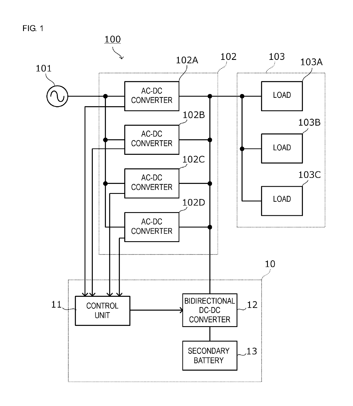
[0062]FIG. 6 is a block diagram of a power supply system according to the The power supply system 100 includes: a converter unit 102 connected to a commercial power supply 101; a load 103; and a battery module 10.

[0063]An OR connection switching element SW is connected to the load-connection side of a bidirectional DC-DC converter 12. The bidirectional DC-DC converter 12 is OR-connected to a bus 9 via the OR connection switching element SW. The OR connection switching element SW is controlled by a current flowing through the OR connection switching element SW and a control signal outputted from the bidirectional DC-DC converter 12. Moreover, the control unit 11 is configured to detect the total output current of the output currents of AC-DC converters 102A, 102B, 102C, and 102D and the bidirectional DC-DC converter 12, that is, a load current, and in turn turn off the OR connection switching element SW when the load current is less than a later-described fourth threshold.

[0064]As f...

first embodiment

[0065]The other configuration is the same as that of the power supply system 100 shown in FIG. 1 in the

[0066]FIG. 7(A) is a circuit diagram of the OR connection switching element SW, and FIG. 7(B) is a circuit diagram of the OR connection switching elements SWa, SWb, SWc, and SWd.

[0067]The OR connection switching element SW shown in FIG. 7(A) includes an OR connection FET Q, a comparator COM, and an AND gate AND. A diode D in the drawing is the body diode of the FET Q. The comparator COM is connected between the drain and the source of the FET Q, and causes the output thereof to be an “H” level when the voltage between the drain and the source satisfies source voltage>drain voltage. The AND gate turns on the FET Q when the output of the comparator COM is an “H” level and a control signal Va is an “H” level.

[0068]The OR connection switching elements SWa, SWb, SWc, and SWd shown in FIG. 7(B) each include an OR connection FET Q and a comparator COM. A diode D in the drawing is the body...


PUM

PropertyMeasurementUnit
DC voltageaaaaaaaaaa
output currentsaaaaaaaaaa

Abstract

A power supply system including a battery module and a converter unit. The system includes a bidirectional DC-DC converter as a component of a battery module voltage control device that is connected between a load and a secondary battery and that changes a discharge voltage of the secondary battery and outputs the discharge voltage to the load. Moreover, a voltage control unit, which can include a control unit and the bidirectional DC-DC converter, changes the discharge voltage of the secondary battery to an output voltage target value to be outputted to the load.

Description

CROSS REFERENCE TO RELATED APPLICATIONS[0001]The present application is a continuation of PCT / JP2017 / 020423 filed Jun. 1, 2017, which claims priority to Japanese Patent Application No. 2016-110980, filed Jun. 2, 2016, the entire contents of each of which are incorporated herein by reference.TECHNICAL FIELD[0002]The present disclosure relates to a battery module that assists in power supply to a load, a voltage control device therefor, and a power supply system including the battery module.BACKGROUND[0003]When a blackout or the like occurs during operation of a computer, various troubles such as data loss and system failure occur. Thus, there is an uninterruptible power supply device that stably supplies power to a load (a computer, etc.) even when a sudden blackout occurs. Patent Document 1 (identified below) discloses an uninterruptible power supply device that performs stable power supply to a load by continuing power supply from a secondary battery to the load during stop of a po...

Claims


Application Information

Patent Timeline
Patent Type & Authority Patents(United States)
IPC IPC(8): H02J7/00H02J7/04H02J9/00H02J3/38H02M3/00G06F1/26H01M10/44H02J3/24H02J3/28H02J3/32H02J3/00G06F1/30H02J3/46
CPCH02J7/045G06F1/263H01M10/44H02J3/24H02J3/28H02J3/32H02J3/38H02J7/0065H02J7/0068H02J9/00H02M3/00H02J2007/0039H02J2003/002H02J3/46H02J3/005G06F1/305Y10T307/625Y10T307/615Y10T307/505Y10T307/511Y10T307/527Y10T307/533H02J9/06H02J1/102H02J7/34H02J7/0063H02J7/007Y02E60/10H02J3/002H02J7/00304H02J2207/20H02J7/00712
Inventor MORI, MICHIYA
Owner MURATA MFG CO LTD
Why Eureka
Try Eureka