Battery module voltage control device, battery module, and power supply system

a battery module and voltage control technology, applied in the direction of secondary cell servicing/maintenance, flasher reduction in ac network, safety/protection circuit, etc., can solve problems such as data loss and system failure, unstable operation, and uninterruptible power supply devices, so as to prevent erroneous load operation and stable voltage

Active Publication Date: 2019-03-28
MURATA MFG CO LTD
View PDF0 Cites 11 Cited by
  • Summary
  • Abstract
  • Description
  • Claims
  • Application Information

AI Technical Summary

Benefits of technology

[0022]According to the exemplary aspects of the present disclosure, it is possible to supply a stable voltage from the battery module to the load even in a heavy load state and when the output voltage of the converter unit has been reduced. As a result, it is possible to prevent erroneous operation of the load due to voltage reduction.

Problems solved by technology

When a blackout or the like occurs during operation of a computer, various troubles such as data loss and system failure occur.
Thus, there is an uninterruptible power supply device that stably supplies power to a load (a computer, etc.) even when a sudden blackout occurs.
However, when the load is an information processing system device, such as a server, a voltage drop may cause unstable operation.
Therefore, the power supply device in Patent Document 1 having constant power drooping characteristics is not suitable as a power supply device for an information processing system device such as a server.

Method used


Image

  • Battery module voltage control device, battery module, and power supply system
  • Battery module voltage control device, battery module, and power supply system
  • Battery module voltage control device, battery module, and power supply system

Examples


first exemplary embodiment

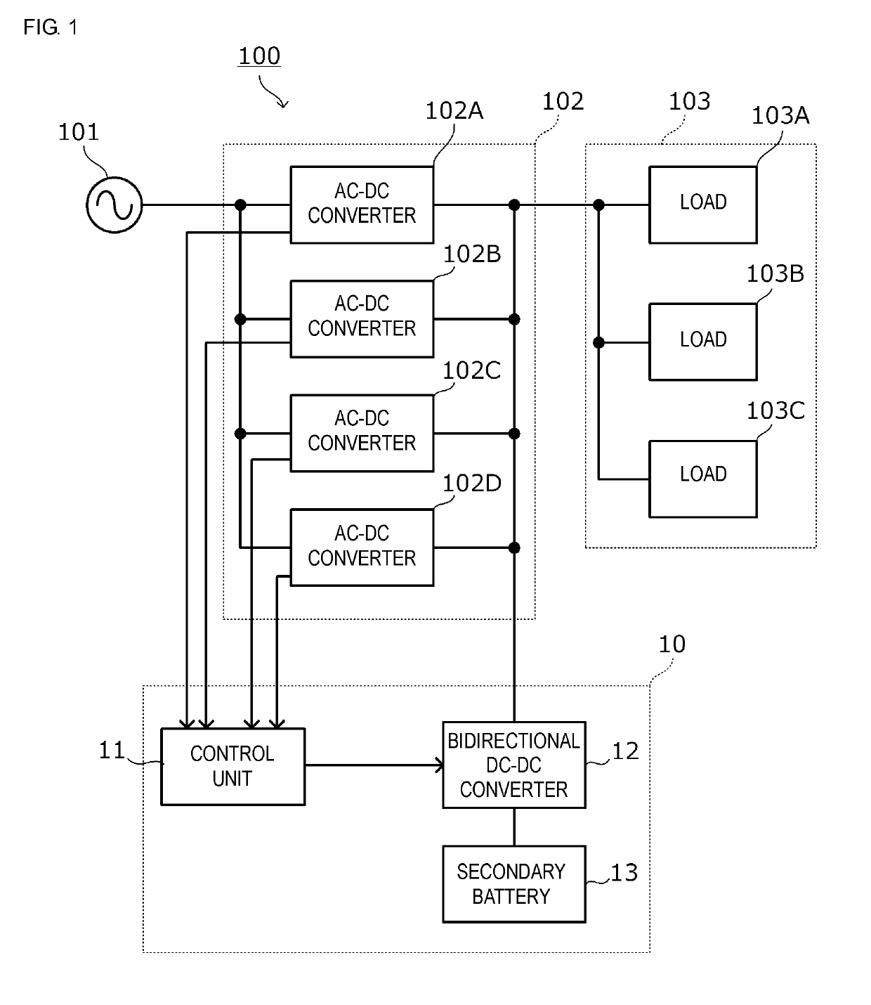
[0032]FIG. 1 is a block diagram of a power supply system 100 according to a first exemplary embodiment.

[0033]As shown, the power supply system 100 includes a converter unit 102 connected to a commercial power supply 101; a load 103; and a battery module 10.

[0034]As an exemplary aspect, the load 103 can include loads 103A, 103B, and 103C. These loads 103A, 103B, and 103C are, for example, blade servers and housed in a housing. The loads 103A, 103B, and 103C are connected in parallel and connected to the converter unit 102. Power is supplied from the converter unit 102 and the battery module 10 to the loads 103A, 103B, and 103C.

[0035]Moreover, the converter unit 102 has an AC-DC converter 102A, an AC-DC converter 102B, an AC-DC converter 102C, and an AC-DC converter 102D. The respective AC-DC converters 102A, 102B, 102C, and 102D are connected in parallel between the commercial power supply 101 and the load 103. Each of the AC-DC converters 102A, 102B, 102C, and 102D is configured to ...

second exemplary embodiment

[0059]In a second exemplary embodiment, an example is provided of a power supply system in which a voltage control unit is OR-connected to a converter unit via an OR connection switching element.

[0060]FIG. 6 is a block diagram of a power supply system according to the second embodiment. The power supply system 100 includes: a converter unit 102 connected to a commercial power supply 101; a load 103; and a battery module 10.

[0061]An OR connection switching element SW is connected to the load-connection side of a bidirectional DC-DC converter 12. The bidirectional DC-DC converter 12 is OR-connected to a bus 9 via the OR connection switching element SW. The OR connection switching element SW is controlled by a current flowing through the OR connection switching element SW and a control signal outputted from the bidirectional DC-DC converter 12. Moreover, the control unit 11 is configured to detect the total output current of the output currents of AC-DC converters 102A, 102B, 102C, and...


PUM

PropertyMeasurementUnit
DC voltageaaaaaaaaaa
output currentsaaaaaaaaaa

Abstract

A power supply system including a battery module and a converter unit. The system includes a bidirectional DC-DC converter as a component of a battery module voltage control device that is connected between a load and a secondary battery and that changes a discharge voltage of the secondary battery and outputs the discharge voltage to the load. Moreover, a voltage control unit, which can include a control unit and the bidirectional DC-DC converter, changes the discharge voltage of the secondary battery to an output voltage target value to be outputted to the load.

Description

CROSS REFERENCE TO RELATED APPLICATIONS[0001]The present application is a continuation of PCT / JP2017 / 020423 filed Jun. 1, 2017, which claims priority to Japanese Patent Application No. 2016-110980, filed Jun. 2, 2016, the entire contents of each of which are incorporated herein by reference.TECHNICAL FIELD[0002]The present disclosure relates to a battery module that assists in power supply to a load, a voltage control device therefor, and a power supply system including the battery module.BACKGROUND[0003]When a blackout or the like occurs during operation of a computer, various troubles such as data loss and system failure occur. Thus, there is an uninterruptible power supply device that stably supplies power to a load (a computer, etc.) even when a sudden blackout occurs. Patent Document 1 (identified below) discloses an uninterruptible power supply device that performs stable power supply to a load by continuing power supply from a secondary battery to the load during stop of a po...

Claims


Application Information

Patent Timeline
Patent Type & Authority Applications(United States)
IPC IPC(8): H02J7/04H02J7/00H01M10/44
CPCH02J2007/0039H02J7/0065H02J3/46H02J2003/002H02J9/00H02J3/28H02J3/005H02J3/24H02J3/32G06F1/305G06F1/263H02J3/38H02J7/0068H01M10/44H02J7/045Y10T307/625Y10T307/615Y10T307/505Y10T307/511Y10T307/527Y10T307/533H02J9/06H02J1/102H02J7/34H02J7/0063H02J7/007Y02E60/10H02J3/002H02J7/00304H02J2207/20H02J7/00712
Inventor MORI, MICHIYA
Owner MURATA MFG CO LTD
Why Eureka
Try Eureka