Method for automatically adjusting a tuning unit, and automatic tuning system using this method

a technology of automatic adjustment and tuning unit, which is applied in the direction of multiple-port active networks, multiple-port networks, impedence matching networks, etc., can solve the problems of inability to automatically adjust the impedance matrix, single-input-output-output-output-output-output-output-output-output-output-output-output-output-output-output-output-output-output-output-ou

Active Publication Date: 2017-03-02
SAMSUNG ELECTRONICS CO LTD
View PDF2 Cites 30 Cited by
  • Summary
  • Abstract
  • Description
  • Claims
  • Application Information

AI Technical Summary

Benefits of technology

[0024]As explained below in the presentations of the second and third embodiments, said m excitations can be used to estimate the q real quantities depending on an impedance matrix seen by the target ports. The specialist understands that this characteristic of the method of the invention cannot be obtained with the plurality of apparatuses for automatically tuning an impedance, used to tune an impedance matrix, as presented above in the prior art section. The specialist also understands that this characteristic of the method of the invention avoids the interferences which wreak havoc on the operation of a plurality of apparatuses for automatically tuning an impedance, used to tune an impedance matrix, in the case where the interactions between the ports of a multiport load coupled to their output ports are not very small.

Problems solved by technology

Here, “passive” is used in the meaning of circuit theory, so that the single-input-port and single-output-port tuning unit does not provide amplification.
We note that, in the apparatuses disclosed in said U.S. Pat. No. 4,356,458 and U.S. Pat. No. 5,225,847, a digital feedback loop involving sequential logic must be used to obtain the tuning control signals and tune the impedance presented by the input port, because the single real quantity depending on the impedance presented by the input port does not provide a full information on the impedance presented by the input port.
Here, “passive” is used in the meaning of circuit theory, so that the multiple-input-port and multiple-output-port tuning unit does not provide amplification.
This approach cannot be used for automatically tuning an impedance matrix, in the case where the interactions between the ports of a multiport load coupled to the output ports are not very small, that is to say in the case where the impedance matrix seen by the output ports is not substantially diagonal.
Unfortunately, this method requires very complex computations or many iterations, because there is no direct relationship between the real quantities depending on the impedance matrix presented by the input ports and the reactance value that each of the adjustable impedance devices should take on after having been adjusted.
Moreover, it can be shown that an adjustment of a multiple-input-port and multiple-output-port tuning unit obtained using this method need not be optimal when the losses in the multiple-input-port and multiple-output-port tuning unit are not very small.
Consequently, there is no known solution to the problem of optimally and automatically adjusting a multiple-input-port and multiple-output-port tuning unit without very complex computations, or without many iterations, or when the losses in the multiple-input-port and multiple-output-port tuning unit are not very small.

Method used


Image

  • Method for automatically adjusting a tuning unit, and automatic tuning system using this method
  • Method for automatically adjusting a tuning unit, and automatic tuning system using this method
  • Method for automatically adjusting a tuning unit, and automatic tuning system using this method

Examples


first embodiment

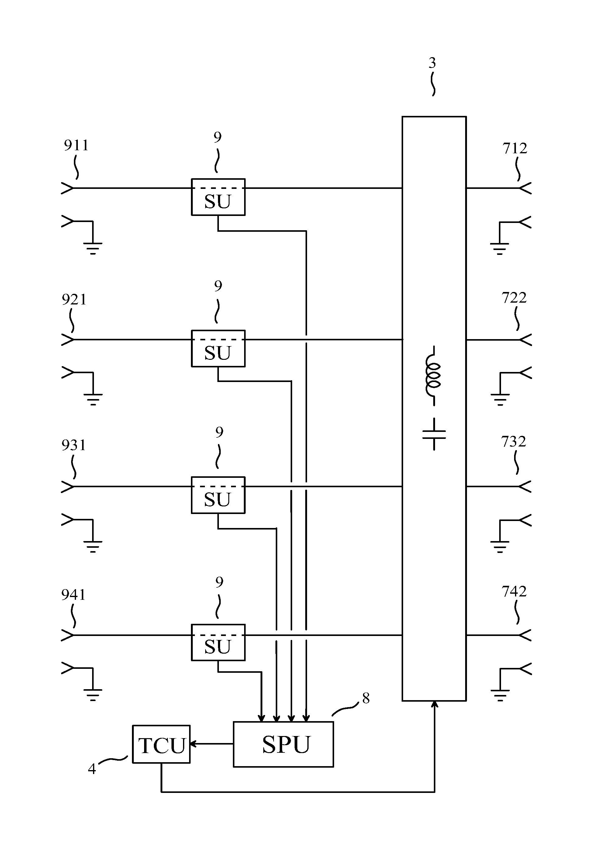
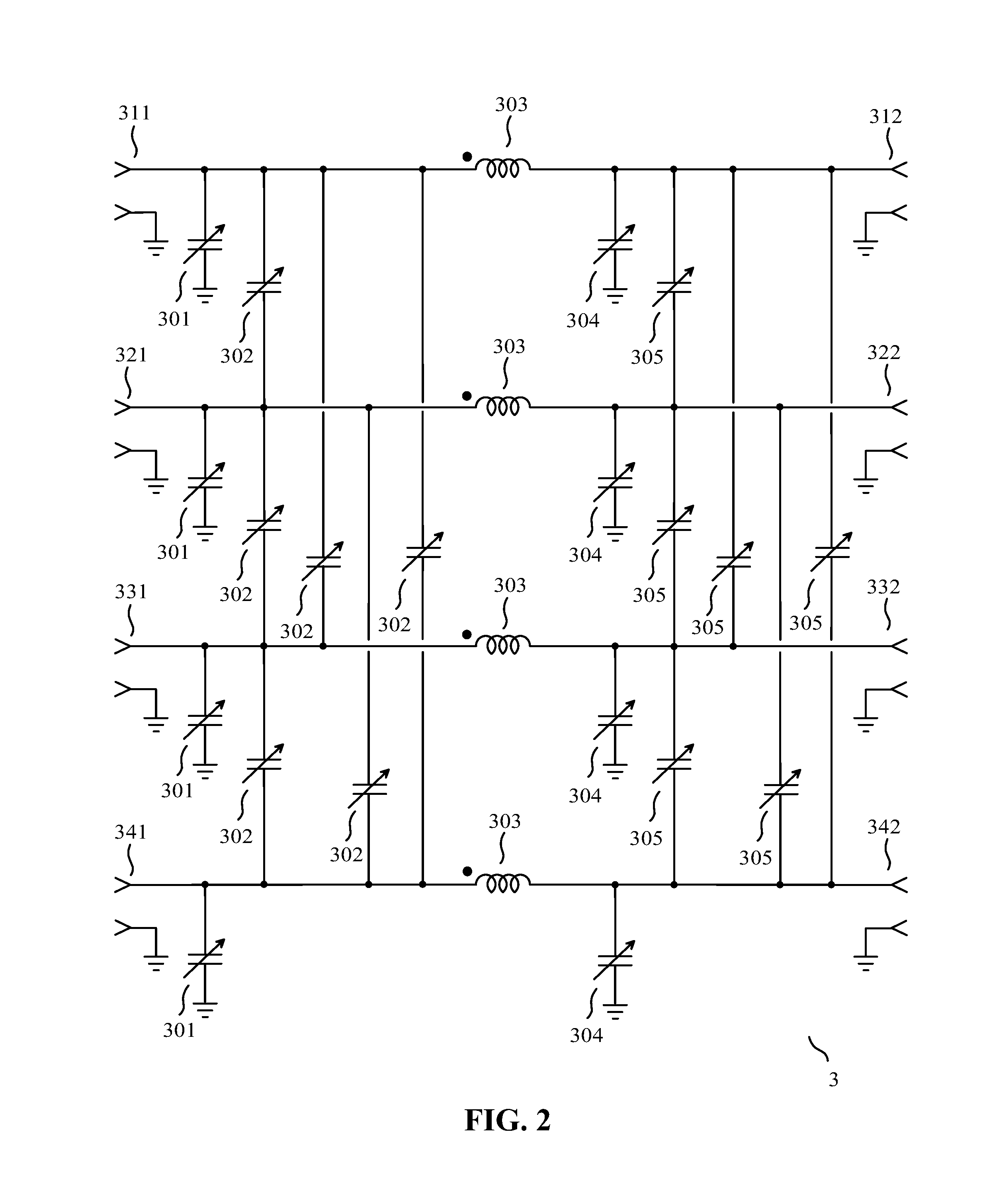
[0053]As a first embodiment of a device of the invention, given by way of non-limiting example, we have represented in FIG. 1 the block diagram of an automatic tuning system having m=4 user ports (712) (722) (732) (742) and n=4 target ports (911) (921) (931) (941), the automatic tuning system allowing, at a given frequency greater than or equal to 30 MHz, a transfer of power from the user ports to the target ports, the automatic tuning system comprising:[0054]n sensing units (9), each of the sensing units delivering two “sensing unit output signals”, each of the sensing unit output signals being determined by one electrical variable;[0055]a signal processing unit (8), the signal processing unit estimating q real quantities depending on an impedance matrix seen by the target ports, where q is an integer greater than or equal to m, using the sensing unit output signals obtained for m excitations applied to the user ports, one and only one of the excitations being applied to each of th...

second embodiment

[0070]The second embodiment of a device of the invention, given by way of non-limiting example, also corresponds to the automatic tuning system having m=4 user ports and n=4 target ports shown in FIG. 1, and all explanations provided for the first embodiment are applicable to this second embodiment. Additionally, in this second embodiment, the m excitations are applied successively to the user ports, that is to say: the m excitations are applied one after another to the user ports. Thus, for instance, it is not possible that two or more of the excitations are applied simultaneously. Each of them excitations applied successively to the user ports may for instance comprise a sinusoidal signal at said given frequency, for instance a sinusoidal current at said given frequency applied to one and only one of the user ports, said one and only one of the user ports being a different user port for each of the m excitations. Each of the m excitations applied successively to the user ports may...

third embodiment

[0079]The third embodiment of a device of the invention, given by way of non-limiting example, also corresponds to the automatic tuning system having m=4 user ports and n=4 target ports shown in FIG. 1, and all explanations provided for the first embodiment are applicable to this third embodiment. Additionally, in this third embodiment, the m excitations are not applied successively to the user ports, that is to say: the m excitations are not applied one after another to the user ports. Thus, for instance, it is possible that two or more of the excitations are applied simultaneously to the user ports. Thus, for instance, it is possible that the m excitations are applied simultaneously to the user ports.

[0080]Moreover, each of the excitations is a bandpass signal. This type of signal is sometimes improperly referred to as “passband signal” or “narrow-band signal” (in French: “signal à bande étroite”). A bandpass signal is any real signal s(t), where t denotes the time, such that the ...


PUM


Abstract

The invention relates to a method for automatically adjusting a multiple-input-port and multiple-output-port tuning unit, for instance a multiple-input-port and multiple-output-port tuning unit coupled to the antennas of a radio transceiver using a plurality of antennas simultaneously. An automatic tuning system using this method has 4 user ports and 4 target ports, and comprises: 4 sensing units; a signal processing unit, the signal processing unit estimating real quantities depending on an impedance matrix seen by the target ports, using sensing unit output signals, the signal processing unit delivering a tuning instruction; a multiple-input-port and multiple-output-port tuning unit comprising adjustable impedance devices; and a tuning control unit receiving the tuning instruction and delivering tuning control signals to the multiple-input-port and multiple-output-port tuning unit, the reactance of each of the adjustable impedance devices being mainly determined by one or more of the tuning control signals.

Description

CROSS REFERENCE TO RELATED APPLICATIONS[0001]This is a Continuation Application of PCT application No. PCT / IB2015 / 057161, filed 17 Sep. 2015, entitled “Method for automatically adjusting a tuning unit, and automatic tuning system using this method”, which in turn claims priority to French patent application No. 15 / 01780 of 26 Aug. 2015, entitled “Procédé pour régler automatiquement une unité d'accord, et système d'accord automatique utilisant ce procédé”, both of which are incorporated herein by reference.FIELD OF THE INVENTION[0002]The invention relates to a method for automatically adjusting a multiple-input-port and multiple-output-port tuning unit, for instance a multiple-input-port and multiple-output-port tuning unit coupled to the antennas of a radio transceiver using a plurality of antennas simultaneously. The invention also relates to an automatic tuning system using this method.PRIOR ART[0003]Tuning an impedance means obtaining that an impedance presented by an input port ...

Claims


Application Information

Patent Timeline
Patent Type & Authority Applications(United States)
IPC IPC(8): H03H11/30H04B1/04
CPCH03H11/30H04B2001/045H04B1/0475H03H7/40H04B1/0458H04B7/0413H01Q5/50H03F1/02H03F3/24H04B1/18
Inventor BROYDE, FREDERICCLAVELIER, EVELYNE
Owner SAMSUNG ELECTRONICS CO LTD
Why Eureka
Try Eureka