Piezoelectric device

a technology of piezoelectric devices and electrodes, applied in the field of piezoelectric devices, can solve the problems of unable to effectively heat the piezoelectric layer and the electrodes, the heater element cannot directly heat the parts on which condensation forms, and the heat generated by the heater element is lost. to achieve the effect of effective heating

Active Publication Date: 2017-03-09
MURATA MFG CO LTD
View PDF5 Cites 8 Cited by
  • Summary
  • Abstract
  • Description
  • Claims
  • Application Information

AI Technical Summary

Benefits of technology

[0016]Since the heater is not in contact with the substrate, it is unlikely that most of the heat generated by the heater will be transmitted to the substrate even when the substrate is a silicon substrate having a large heat capacity and therefore the piezoelectric layer and the electrodes, which are to be heated, can be effectively heated. In other words, there is little loss of the heat generated by the heater.

Problems solved by technology

However, the piezoelectric devices described in Patent Documents 2 and 3 have the following problems.
Problem 1—Most of the heat generated by a heater element is transmitted to the substrate when the substrate is a silicon substrate having a large heat capacity since the heater element is in contact with the substrate, and therefore the heater element cannot effectively heat the piezoelectric layer and the electrodes, which are to be heated.
In other words, much of the heat generated by the heater element is lost.
Problem 2—Although condensation may form on the surfaces of the piezoelectric layer and electrodes, since the heater element is arranged on the substrate, the heater element cannot directly heat the parts on which condensation forms.
Problem 3—A manufacturing step for forming the heater element is specially needed and the manufacturing process consequently becomes more complex.

Method used


Image

  • Piezoelectric device
  • Piezoelectric device
  • Piezoelectric device

Examples


embodiment 1

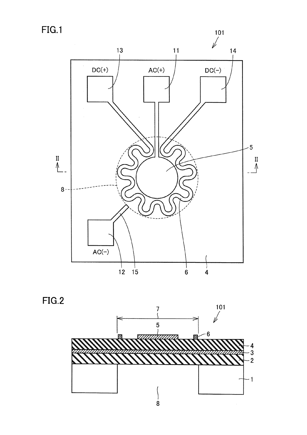
[0033]A piezoelectric device according to embodiment 1 of the present invention will be described while referring to FIGS. 1 and 2. FIG. 2 is a sectional view looking in the direction of arrows and taken along line II-II in FIG. 1.

[0034]A piezoelectric device 101 of this embodiment includes: a substrate 1 defining an opening 8 therein; a piezoelectric layer 4 that is directly or indirectly supported by the substrate 1 and is arranged above the substrate 1 such that at least part of the piezoelectric layer 4 is included in a membrane part 7 that is not superimposed with the substrate 1; a lower electrode 3 that is arranged below the piezoelectric layer 4 in at least the membrane part 7; and an upper electrode 5 that is arranged above the piezoelectric layer 4 so as to face at least part of the lower electrode 3 with the piezoelectric layer 4 interposed therebetween in the membrane part 7. A heater 6 is arranged above the piezoelectric layer 4 so as to be separate from the upper elect...

embodiment 2

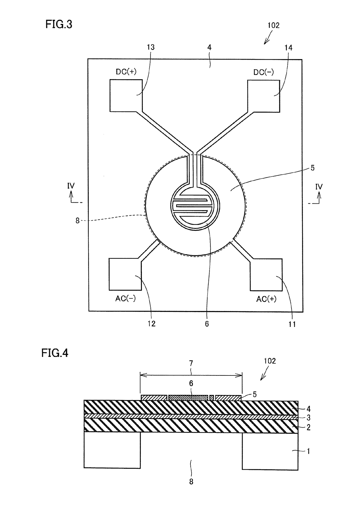
[0059]A piezoelectric device according to embodiment 2 of the present invention will be described while referring to FIGS. 3 and 4. FIG. 4 is a sectional view looking in the direction of arrows and taken along line IV-IV in FIG. 3.

[0060]The basic configuration of a piezoelectric device 102 according to this embodiment is similar to that of the piezoelectric device 101 described in embodiment 1. In embodiment 1, the entirety of the upper electrode 5 functions as a driving / detection electrode, the upper electrode 5 is provided in a central portion of the projected area of the through hole 8 and the heater 6 is provided so as to surround the periphery of the upper electrode 5, which functions as a driving / detection electrode. In contrast, in this embodiment, conversely, the heater 6 is arranged in the center of the projected area of the through hole 8 and the upper electrode 5, which can function as a driving / detection electrode, is provided so as to surround the periphery of the heate...

embodiment 3

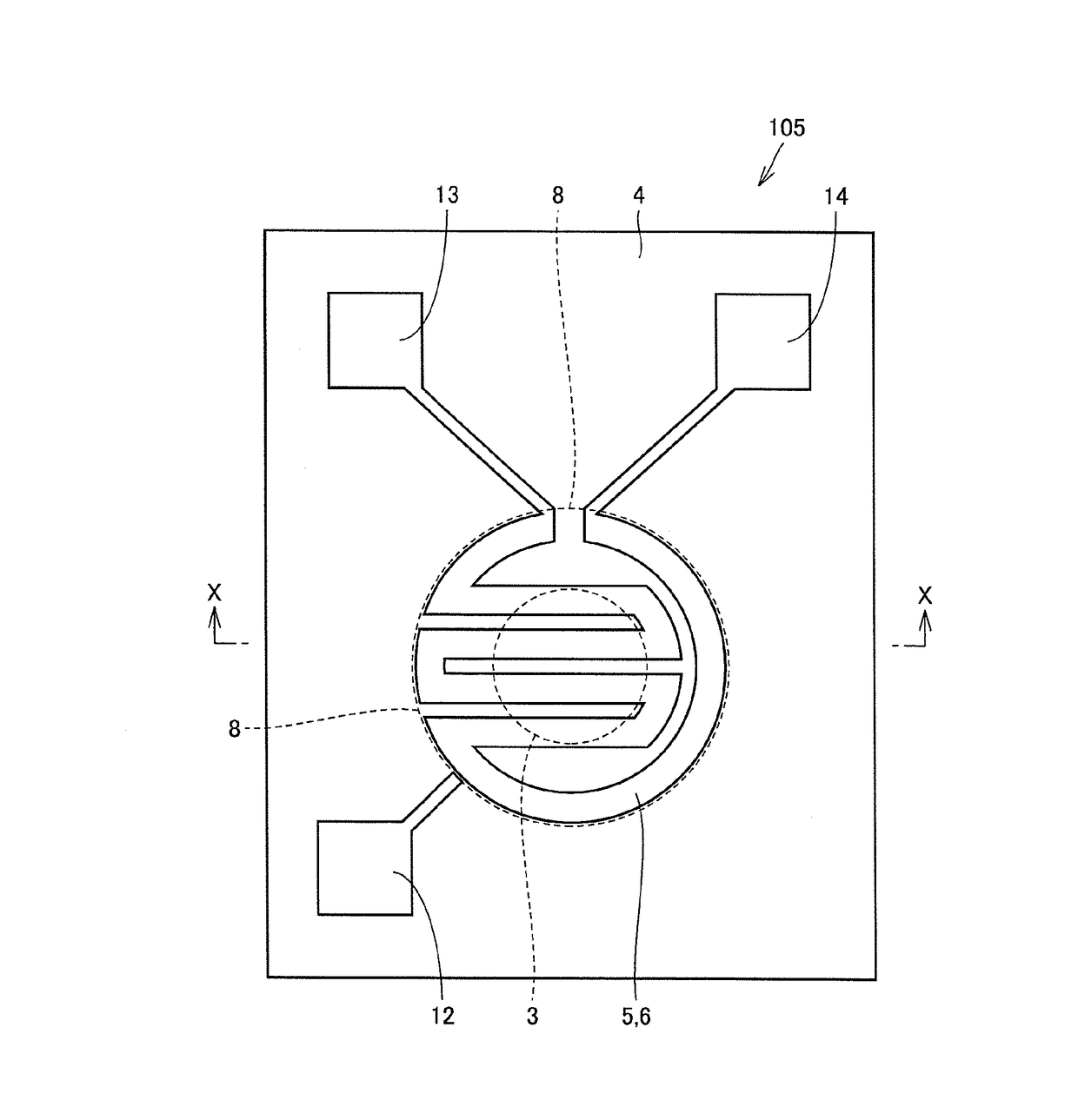
[0063]A piezoelectric device according to embodiment 3 of the present invention will be described while referring to FIGS. 5 and 6. FIG. 6 is a sectional view looking in the direction of arrows and taken along line VI-VI in FIG. 5.

[0064]The basic configuration of a piezoelectric device 103 according to this embodiment is similar to that of the piezoelectric device 101 described in embodiment 1. However, there is the following difference. In the piezoelectric device 103, rather than the heater 6 being arranged above the piezoelectric layer 4 so as to be separate from the upper electrode 5, the upper electrode 5 doubles as the heater 6.

[0065]The upper electrode 5 / heater 6 is arranged so as to extend along the outer edge of the through hole 8 in plan view. The upper electrode 5 / heater 6 has a meandering shape in plan view. Since the upper electrode 5 faces the lower electrode 3 when the upper electrode 5 is formed in this way as well, the upper electrode 5 can function as a driving ele...


PUM


Abstract

A piezoelectric device that includes a substrate defining an opening therein; a piezoelectric layer arranged above the substrate such that at least part of the piezoelectric layer extends over the opening and forms a membrane part that is not superimposed with the substrate; a lower electrode arranged below the piezoelectric layer in at least the membrane part; and an upper electrode that is arranged above the piezoelectric layer so as to face at least part of the lower electrode with the piezoelectric layer interposed therebetween in the membrane part. A heater is arranged above the piezoelectric layer so as to be separate from the upper electrode or at least part of the upper electrode doubles as a heater.

Description

CROSS REFERENCE TO RELATED APPLICATIONS[0001]The present application is a continuation of International application No. PCT / JP2015 / 065591, filed May 29, 2015, which claims priority to Japanese Patent Application No. 2014-121564, filed Jun. 12, 2014, the entire contents of each of which are incorporated herein by reference.FIELD OF THE INVENTION[0002]The present invention relates to piezoelectric devices.BACKGROUND OF THE INVENTION[0003]In the related art, a piezoelectric device is known that includes a substrate, a piezoelectric layer that is provided above the substrate and electrodes that are arranged such that the piezoelectric layer is interposed between the electrodes, as described in Japanese Unexamined Patent Application Publication No. 2009-260723 (Patent Document 1) for example. Such a piezoelectric device is used in filters, actuators, sensors and so forth.[0004]As an example of such a piezoelectric device, a MEMS device that includes a transducer, a substrate and a temper...

Claims


Application Information

Patent Timeline
Patent Type & Authority Applications(United States)
IPC IPC(8): H01L41/047H01L41/18H01L41/113H01L41/09
CPCH01L41/0471H01L41/1138H01L41/18H01L41/0973H04R17/00H04R17/02H10N30/87H10N30/2047H10N30/853H10N30/871H10N30/20H10N30/30H10N30/80H10N30/85H10N30/308
Inventor MOURI, TAKAOYAMAMOTO, KANSHO
Owner MURATA MFG CO LTD
Why Eureka
Try Eureka