Conduction-breaking device

a technology of conductive body which is applied in the direction of electric devices, propulsion by batteries/cells, transportation and packaging, etc., can solve the problems of conductive body melting and surrounding plastic parts, and the device of the publication is therefore susceptible to improvement in terms of attenuation, so as to improve the attenuation effect

Active Publication Date: 2017-03-16
TOYODA GOSEI CO LTD
View PDF6 Cites 16 Cited by
  • Summary
  • Abstract
  • Description
  • Claims
  • Application Information

AI Technical Summary

Benefits of technology

[0009]Accordingly, it is an objective of the present invention to improve the attenuation effect in a conduction-breaking device that cuts a cuttable portion at two positions.

Problems solved by technology

Further, the arc may melt the conductive body and its surrounding plastic members.
The device of the publication is therefore susceptible to improvement in terms of attenuation of arcs.

Method used


Image

  • Conduction-breaking device
  • Conduction-breaking device
  • Conduction-breaking device

Examples


first embodiment

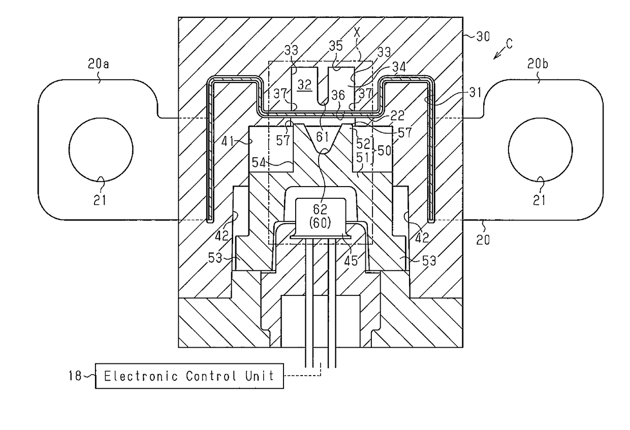
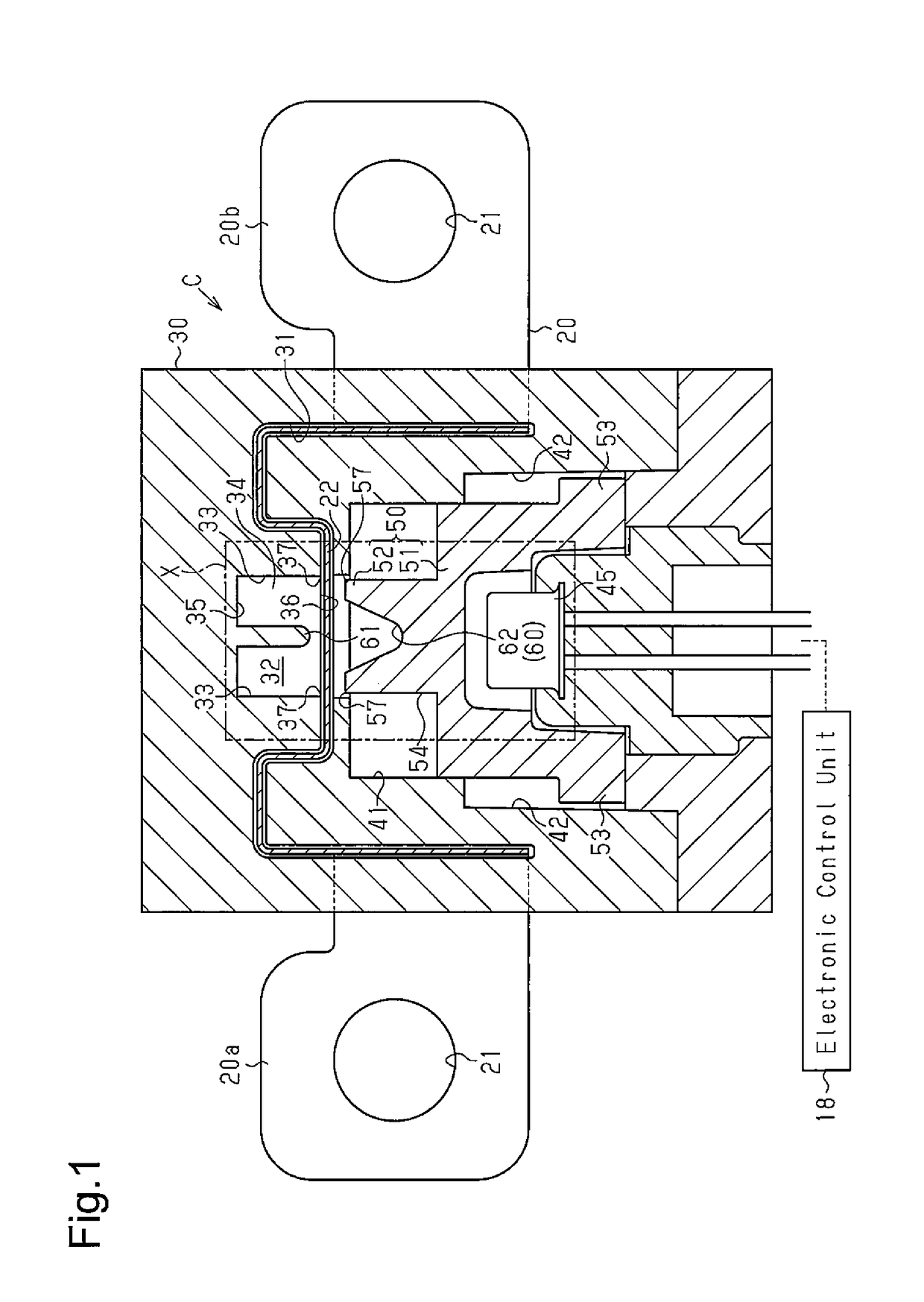
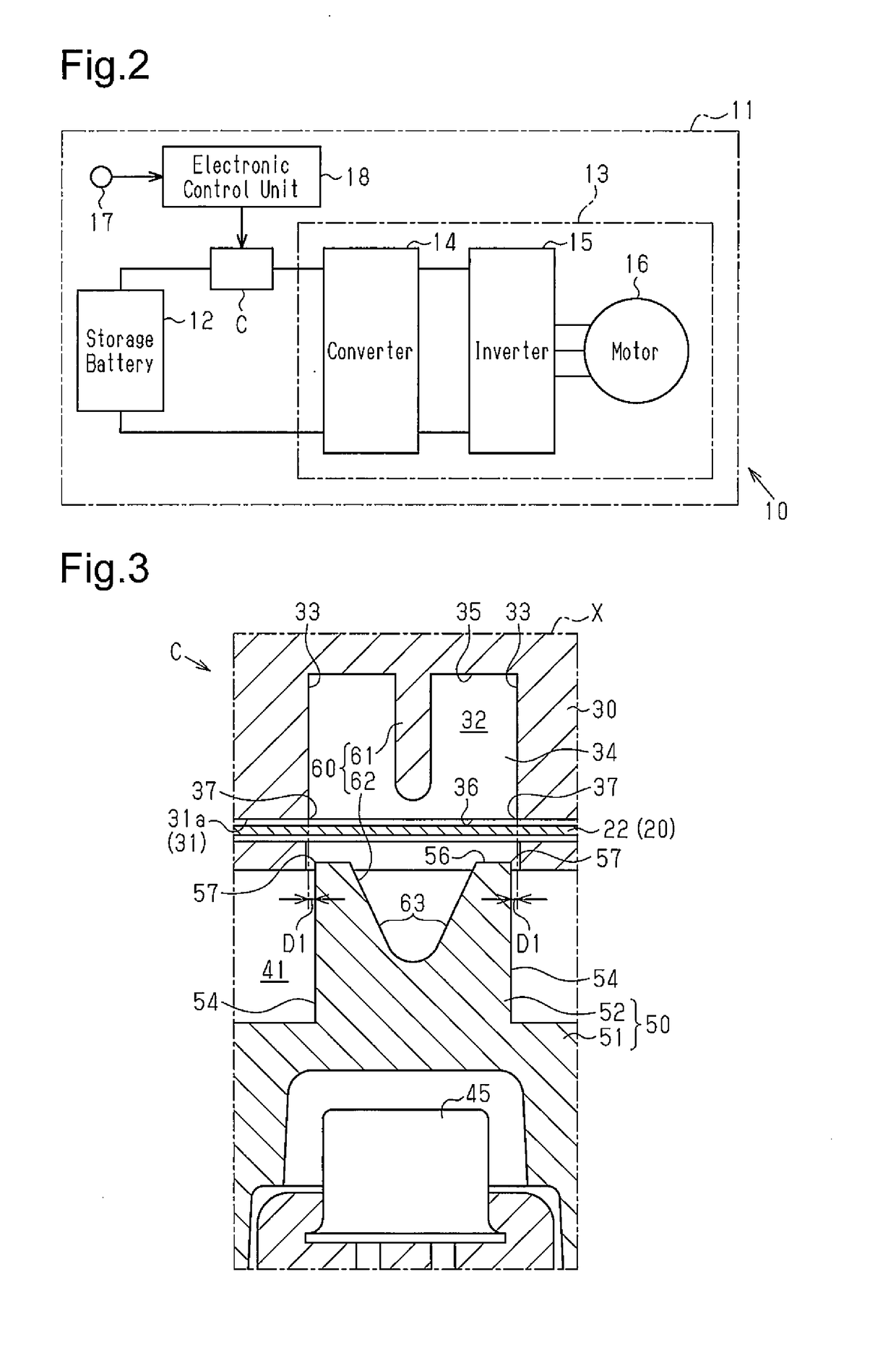
[0024]A conduction-breaking device C for a vehicle according to a first embodiment will now be described with reference to FIGS. 1 to 6.

[0025]FIG. 2 shows an electric circuit 11 in which the conduction-breaking device C is incorporated. The electric circuit 11 includes as its components a storage battery 12 and an electric device 13. In the electric circuit 11, the electric device 13 is operated by power supplied from the storage battery 12. The electric device 13 is configured by a converter 14, which increases the voltage of the power delivered from the storage battery 12 and outputs power of the increased voltage, an inverter 15, which converts DC power from the converter 14 into AC power suitable for driving a motor and outputs the AC power, and a motor 16, which is driven by the AC power output from the inverter 15.

[0026]The electric circuit 11 is mounted on a vehicle 10. When the vehicle 10 receives an impact due to a collision, the electric device 13 may not properly operate,...

second embodiment

[0078]A conduction-breaking device C for a vehicle according to a second embodiment will now be described with reference to FIGS. 7 and 8.

[0079]In the second embodiment, the securing mechanism 70 is replaced by a first holding mechanism 80. The first holding mechanism 80 holds the separated piece 23, which has been deformed by the restricting portion 61 and the recess 62, in a state of being held in contact with the restricting portion 61. The first holding mechanism 80 includes a columnar engaging projection 81 provided in the restricting portion 61 and an engagement portion 82 in the cuttable portion 22. The engaging projection 81 projects toward the gas generator 45 from the end of the restricting portion 61 closer to the gas generator 45. The engaging projection 81 is provided at the end of the restricting portion 61 closer to the gas generator 45, specifically, in a part of that end in the width direction of the cuttable portion 22. A plurality of engaging projections 81 and a ...

third embodiment

[0091]A conduction-breaking device C for a vehicle according to a third embodiment will now be described with reference to FIGS. 9 to 11.

[0092]In the third embodiment, a second holding mechanism 90 is further provided, which holds the separated piece 23, which has been deformed by the restricting portion 61 and the recess 62, in a state of being held in contact with the inner wall surfaces of the recess 62.

[0093]As shown in FIG. 9, the second holding mechanism 90 includes a pair of restricting pieces 91 provided in the blade portion 52 of the cutting member 50. Each restricting piece 91 is provided at the boundary between of one of the inclined surfaces 63 in the recess 62 and the corresponding outer end wall surface 56 of the blade portion 52. Each restricting piece 91 projects toward the other facing restricting piece 91. The restricting pieces 91 reduces the dimension of the recess 62 along the length of the cuttable portion 22 at the outer end wall surfaces 56 compared to a case...


PUM


Abstract

A conduction-breaking device breaks conduction between a pair of devices in an electric circuit. The conduction-breaking device includes a conductive body having a cuttable portion, an arc-extinguishing chamber having a pair of fixed blades, a gas generator, a cutting member having a pair of movable blades, and a deforming mechanism. When the cuttable portion is cut at two positions by the fixed blades and the movable blades, the cuttable portion forms a separated piece, which is separated from the electric circuit, and first and second remaining portions, which remain connected with the electric circuit. The separated piece has cut ends at opposite ends. The deforming mechanism deforms the separated piece such that the cut ends of the separated piece are located on a leading side in a moving direction of the cutting member with respect to a part of the separated piece between the cut ends.

Description

BACKGROUND OF THE INVENTION[0001]The present invention relates to a conduction-breaking device that breaks conduction between two devices constituting an electric circuit by cutting a conductive body extending between the devices.[0002]Some electric circuits are provided with a conduction-breaking device for breaking conduction between devices by being activated when a malfunction occurs in a device in the electric circuit or in a system on which the electric circuit is mounted. As one form of such conduction-breaking devices, Japanese Laid-Open Patent Publication No. 2012-138286 discloses a conduction-breaking device, which includes a conductive body, an arc-extinguishing chamber, a gas generator, and a cutting member.[0003]The conductive body includes an elongated plate-shaped cuttable portion and is arranged between devices that constitute an electric circuit. The arc-extinguishing chamber has a fixed blade and is provided on one side of the cuttable portion in the thickness dire...

Claims


Application Information

Patent Timeline
Patent Type & Authority Applications(United States)
IPC IPC(8): H01H39/00B60L11/18H01H33/72B60L50/15
CPCH01H39/006B60L2210/40B60L11/1879H01H33/72H01H39/00H01H2039/008B60L3/0007B60L50/64Y02T10/70
Inventor HORI, KEISUKENAKAMURA, YOSHIKIFUKUYAMA, TAKAKI
Owner TOYODA GOSEI CO LTD
Why Eureka
Try Eureka