System and method for providing real-time visual feedback to control multiple autonomous nano-robots

Inactive Publication Date: 2017-03-16
JORDAN UNIVERSITY OF SCIENCE AND TECHNOLOGY
View PDF4 Cites 0 Cited by
  • Summary
  • Abstract
  • Description
  • Claims
  • Application Information

AI Technical Summary

Benefits of technology

[0014]As another object of the present invention, there is provided a system and method th

Problems solved by technology

None of the prior art documents provides a system and method for providing real-time visual f

Method used


Image

  • System and method for providing real-time visual feedback to control multiple autonomous nano-robots
  • System and method for providing real-time visual feedback to control multiple autonomous nano-robots
  • System and method for providing real-time visual feedback to control multiple autonomous nano-robots

Examples


Embodiment Construction

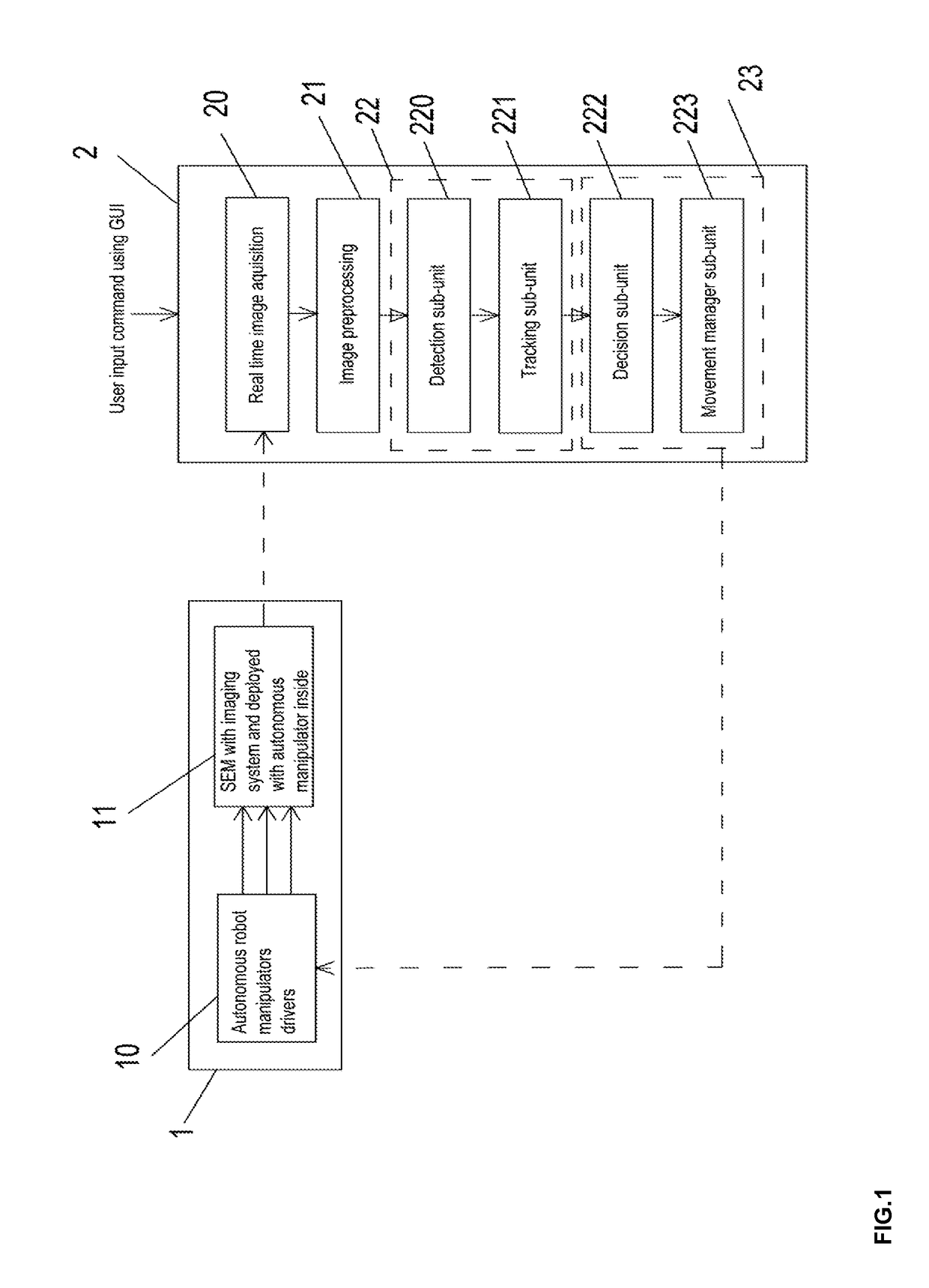
[0044]FIGS. 1-17 illustrate a system and method for providing real-time visual feedback to control the actions of multiple nano-robots using Scanning Electron Microscopy (SEM) for enabling the manipulation / assembly of hybrid nano-components and particles configured in accordance with a preferred embodiment of the present invention, wherein such embodiment comprises at least one slave SEM with imaging system deployed with autonomous manipulators inside 1, and at least one master controller with a Graphical User Interface (GUI) 2. In the preferred embodiment of the present invention, said at least one slave SEM 1 provides real-time visual feedback for the sensed environment for the said at least one master controller 2, and said at least one master controller 2 provides real-time feedback control command for the required task to the said at least one slave SEM 1.

[0045]In the preferred embodiment of the present invention, said at least one master controller 2 comprises a GUI unit (not ...


PUM


Abstract

The present invention relates to a system and method for providing real-time visual feedback to automatically control actions of multiple autonomous nano-robots with manipulators in order to perform specific nano-manipulation or nano-assembly tasks. In the system and method of the present invention, the visual feedback is obtained for the nano-manipulators and the nano-components via an electronic microscopy system. The system of the present invention comprises essentially at least one slave Scanning Electron Microscope (SEM) with imaging system deployed with autonomous manipulators inside, and a master controller system with Graphical User Interface (GUI). In the system of the present invention, said slave SEM provides real-time vision feedback for the sensed environment for said master controller, and said master controller provides real-time feedback control command for the required task to said slave SEM.

Description

BACKGROUND[0001]Field of the Invention[0002]The present invention relates to systems and methods used for providing real-time visual feedback to automatically control actions of multiple autonomous robots, and more particularly to those systems and methods that control actions of nano-robots with nano-manipulators.[0003]Description of the Related Art[0004]Numerous conventional solutions found in the art provide systems and methods of controlling actions of robots to enable manipulation tasks. Among such conventional solutions lie the US patent number 6,967,335, the U.S. Pat. No. 7,297,946, U.S. Pat. No. 6,891,170, U.S. Pat. No. 6,862,924, the European project titled “Smart and small robots for the micro-world”, the scientific article titled “Microrobot system for automatic nanohandling inside a scanning electron microscope” by Fatikow, S., et al published on May, 2006, and the scientific article titled “Microrobot system for automatic nanohandling inside a scanning electron microsco...

Claims


Application Information

Patent Timeline
IPC IPC(8): H01J37/20H01J37/28
CPCH01J37/20H01J2237/28H01J37/28B25J7/00B82Y99/00H01J2237/208
Inventor AL-FANDI, MOHAMED GHAZI DAIFALLAAL ROUSAN, MOHAMMAD ABDEL MAJEEDFANDIJARADAT, MOHAMMAD ABDEL KAREEM RASHEEDAWAD, FAHED HASAN FAHEDALJARRAH, INAD ABEDALMOHDI RIDAAL-JARRAH, OMAR MAHMOUD MOHAMMAD
Owner JORDAN UNIVERSITY OF SCIENCE AND TECHNOLOGY
Why Eureka
Try Eureka