Wearable camera system and recording control method

a camera system and wearable technology, applied in the field of wearable camera systems and recording control methods, can solve the problems of poor service quality, large trouble, and difficulty in early resolution of incidents, and achieve the effect of efficient assistance for police officers in their services

Active Publication Date: 2017-03-23
PANASONIC I PRO SENSING SOLUTIONS CO LTD
View PDF8 Cites 11 Cited by
  • Summary
  • Abstract
  • Description
  • Claims
  • Application Information

AI Technical Summary

Benefits of technology

[0008]The present disclosure is made in consideration of the above described circumstances, and an object thereof is to provide a wearable camera system which efficiently assists police officers with their services by starting recording of a video captured by a wearable camera so as to prevent the recording from missing even if a police officer does not perform a recording operation in person when an incident happens, and a method of controlling recording.

Problems solved by technology

However, in the configuration disclosed in Japanese Patent Unexamined Publication No. 2006-148842, in a case where an incident suddenly happens, a police officer is required to promptly take various actions with respect to the incident in consideration that an initial operation or an initial investigation is important, and if the police officer cannot afford to press a recording switch of the wearable camera in a site of an incident and thus forgets to record a video, there may be missing of the recording as a result.
That is, there is a problem in that it is not possible to remain recording of an evidence video for a site or a suspect involved in an incident in the wearable camera, and thus the video of the incident site cannot be obtained, a district police office cannot take quick and appropriate actions with respect to the occurrence of the incident, and thereby early resolution of the incident may become difficult.
In addition, if the recording of the evidence video cannot be performed, it is not possible to present sufficient evidence in court afterward, and as a result, there is a possibility of causing a great deal of trouble.

Method used


Image

  • Wearable camera system and recording control method
  • Wearable camera system and recording control method
  • Wearable camera system and recording control method

Examples


first embodiment

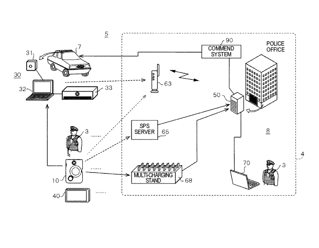
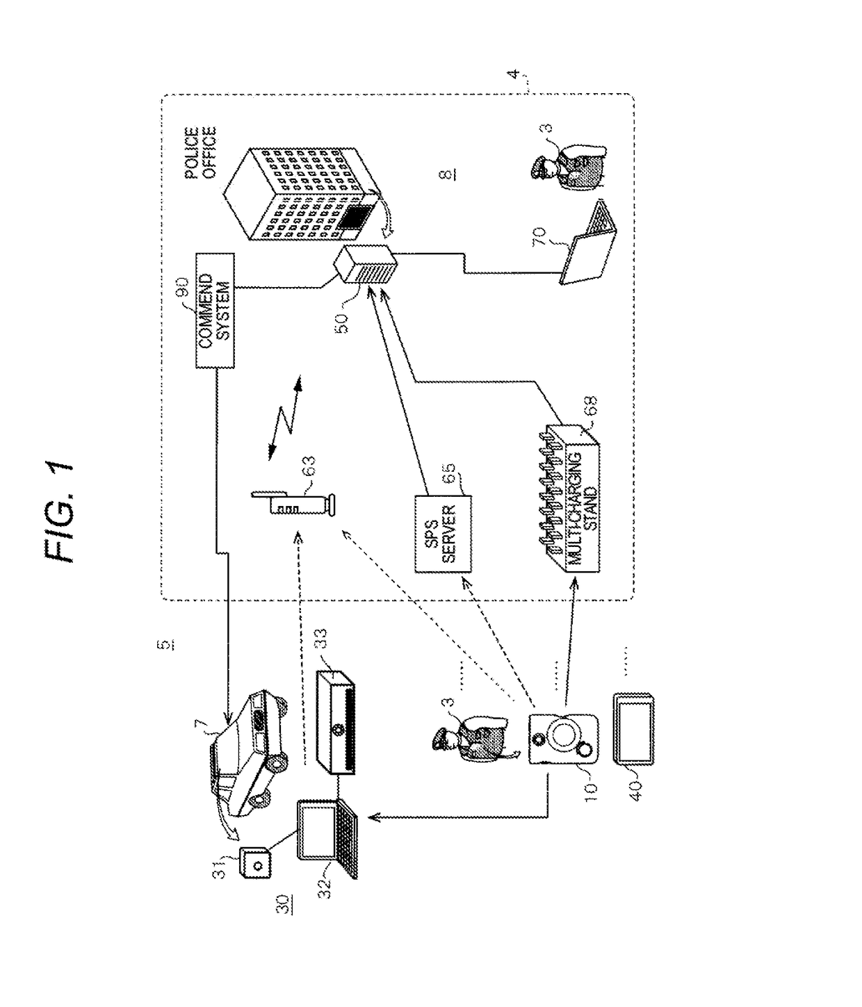
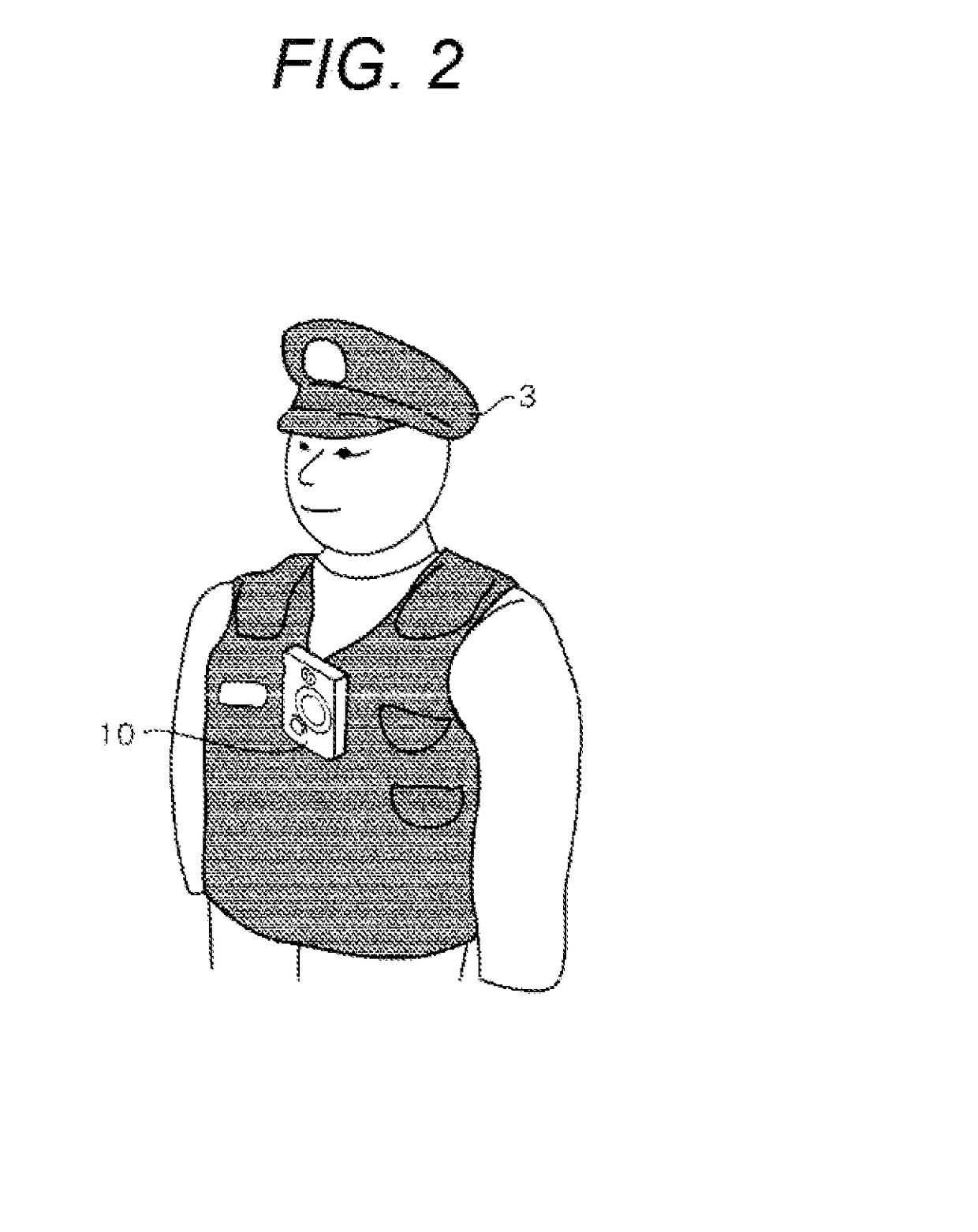
[0025]FIG. 1 is an explanatory diagram illustrating an example of an outline of wearable camera system 5 of the exemplary embodiments. Wearable camera system 5 is configured to include on-vehicle camera system (in car video system (ICV)) 30 which is mounted on patrol car 7, wearable camera 10 which is mounted on a uniform of police officer 3, and in-office system 8 installed in the inside of police office 4.

[0026]On-vehicle camera system 30 includes one or more of on-vehicle cameras 31, on-vehicle personal computer (PC) 32, and on-vehicle recorder 33, and captures a video based on captured images of an incident happened when police officers patrol by driving patrol car 7 so as to record the incident. One or more of on-vehicle cameras 31 include one or more cameras among a camera which is installed so as to capture the front of a patrol car 7, and cameras which are respectively installed so as to capture the left, the right, and the rear of the patrol car. On-vehicle PC 32 controls o...

second exemplary embodiment

[0127]In the first exemplary embodiment, the case where the wearable camera is usually connected to the back end server of the police office via the network is described; however, in the second exemplary embodiment, a case where the wearable camera is not connected to the network in general will be described. In this case, a police officer in the outside of the police office and a police officer in the police office make a call using a radio wave.

[0128]The wearable camera system in the second exemplary embodiment has almost the same configuration as that of the first exemplary embodiment. The same components as those in the first exemplary embodiment are denoted by the same reference numerals, and thus the description thereof will be omitted.

[0129]FIG. 9 is a block diagram illustrating an example of an internal configuration of wearable camera 10A of the second exemplary embodiment. In wearable camera 10A, storage 15 includes audio database 15y in which the predetermined audio data ...

first exemplary embodiment

Modification Example 2 of First Exemplary Embodiment

[0151]Modification example 2 of the first exemplary embodiment (hereinafter, referred to as Modification example 2) describes a case where command system 90 notifies wearable camera 10 of the automatic start of the recording via an on-vehicle PC, a tablet, or a smart phone (hereinafter, referred to as a mobile terminal) which is belongs to the police officer. Note that, command system 90 may notify on-vehicle PC 32 of on-vehicle camera system 30 of the automatic start of the recording in addition to the aforementioned mobile terminal such as the tablet and the smart phone. In this case, on-vehicle PC 32 can instruct wearable camera 10 to perform the automatic start of the recording.

[0152]FIG. 11B is a diagram illustrating automatic recording in Modification example 2. Wearable camera 10 can communicate with the mobile terminal. This type of communication is performed via a USB cable, Bluetooth (trade mark), near field communication...


PUM

PropertyMeasurementUnit
timeaaaaaaaaaa
structureaaaaaaaaaa
time seriesaaaaaaaaaa

Abstract

A detector in MCU generates audio data by cutting out a section of the sounds collected by a microphone. A communicator transmits the generated audio data to a back end server. The back end server receives the audio data from a wearable camera. CPU collates the received audio data with audio data registered in an audio database. The communicator notifies the wearable camera of automatic start of the recording in a case where the received audio data and the registered audio data are matched with each other, as a result of collation. In a case of being notified of the instruction to start the recording from the server, the wearable camera starts the recording of a video captured by a capture.

Description

BACKGROUND[0001]Technical Field[0002]The present disclosure relates to a wearable camera system which controls recording of a video captured by a wearable camera and a recording control method.[0003]Description of the Related Art[0004]Recently, in order to efficiently assist police officers with their services, a system in which police officers have a wearable camera mounted on a uniform or carry a wearable camera at the time of patrolling, for example has been examined.[0005]As a related art using a wearable camera, a wearable monitoring camera system disclosed in Japanese Patent Unexamined Publication No. 2006-148842 is exemplified. The wearable monitoring camera system disclosed in Japanese Patent Unexamined Publication No. 2006-148842 has a configuration in which an image (video) signal and a sound signal from a CCD camera and a microphone which are wearable, and a date and time information signal from a built-in clock are encoded by an encoding server which can be accommodated ...

Claims


Application Information

Patent Timeline
Patent Type & Authority Applications(United States)
IPC IPC(8): H04N5/77H04N5/225H04N21/6543H04N21/422H04N21/4223G11B20/10H04N21/2743H04N5/91
CPCH04N5/77H04N21/2743H04N5/2251H04N5/91G11B2020/10537H04N21/4223G11B20/10527H04N21/6543H04N21/42203H04N9/802H04N23/50H04N23/661
Inventor WANIGUCHI, KAZUYAHAGIO, MINORU
Owner PANASONIC I PRO SENSING SOLUTIONS CO LTD
Why Eureka
Try Eureka