
Elevating Support For Viewing Electronic Displays

a technology for electronic displays and supports, which is applied in the direction of rod connections, casings/cabinets/drawers, and electric apparatus details. it can solve the problems of unsatisfactory stress on the spine, excessive stress on the spine nick section, and excessive head weight, etc., and achieves the effect of convenient carrying

Inactive Publication Date: 2017-03-23
SIMON DAVID F
View PDF3 Cites 18 Cited by
  • Summary
  • Abstract
  • Description
  • Claims
  • Application Information

AI Technical Summary

Benefits of technology

This patent describes an elevating support for electronic devices that can be easily carried and used while sitting or reclining. The support includes an upright elongated member that holds the device at a comfortable elevated position, eliminating the need to tilt the neck to view the display. The support also has a base piece that is held under the user's thigh to keep them comfortable for extended periods. The elevating support can swing forward or rearward, or inward or outward from the user. Additionally, the cradle that holds the device allows for swiveling and adjustable orientation.

Problems solved by technology

Sustained tilted neck positioning causes undesirable stress on one's spine particularly in the upper part thereof.
When the neck is inclined for lengthy periods, the weight of the head exerts an excessive undesirable stress on the spine nick section.
This stress may cause pain and even injury to a person's spine such that the person develops a stooped posture, which posture further stresses the person's spine.
However, selfies are often taken when a person is out and about and tripods are usually deemed to be too bulky to be carried.
Another disadvantage of the tripod is that the inclined legs create obstacles when the person or subject attempts to be positioned close to the device, as for reading when seated in a chair or reclining in a bed or sofa.
Furthermore, conventional tripods offer only limited capability to adjust the position or orientation of the device.

Method used


Image

  • Elevating Support For Viewing Electronic Displays
  • Elevating Support For Viewing Electronic Displays
  • Elevating Support For Viewing Electronic Displays

Examples


Embodiment Construction

[0028]In the following detailed description, certain specific terminology will be employed for the sake of clarity and a particular embodiment described in accordance with the requirements of 35 USC 112, but it is to be understood that the same is not intended to be limiting and should not be so construed inasmuch as the invention is capable of taking many forms and variations within the scope of the appended claims.

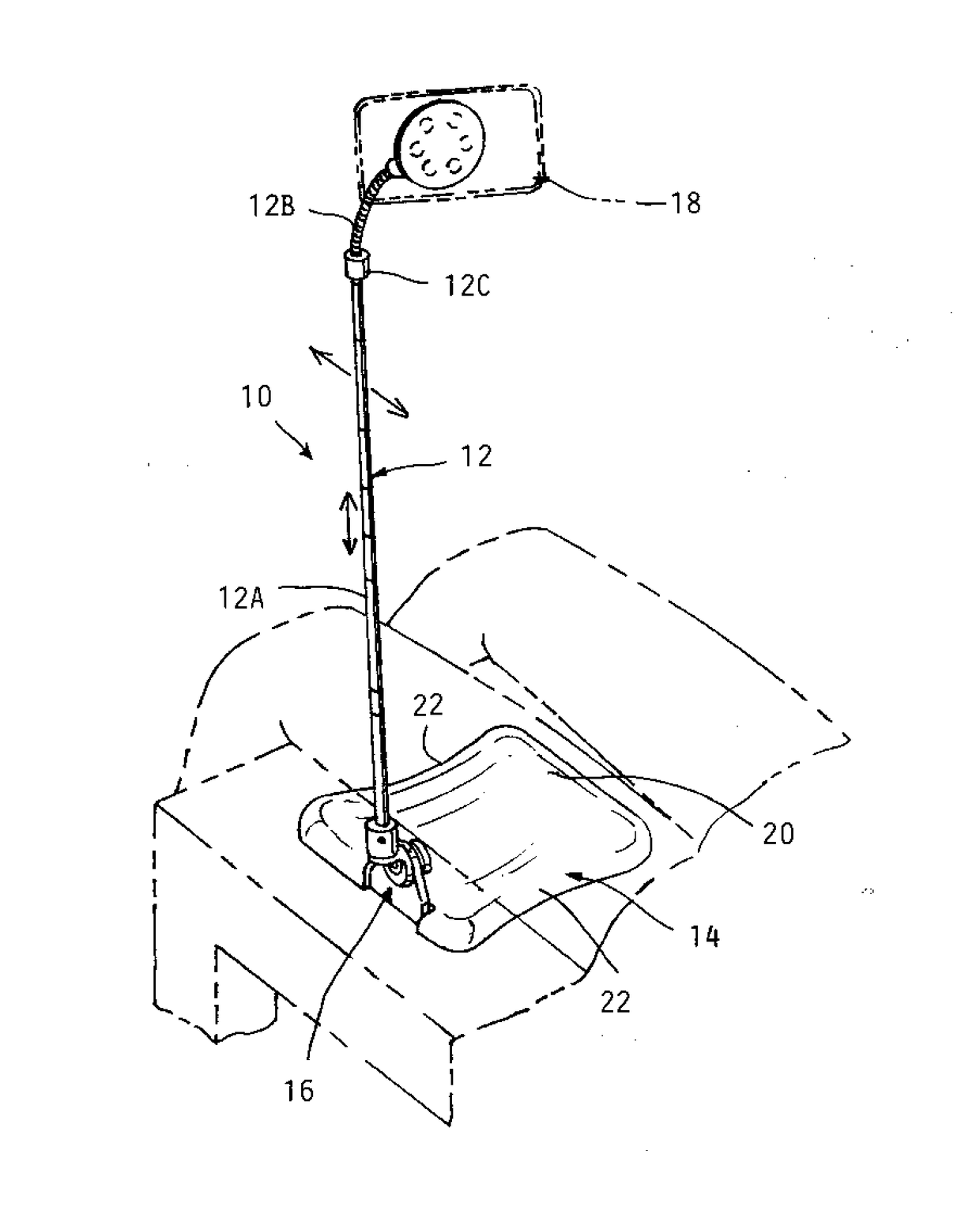
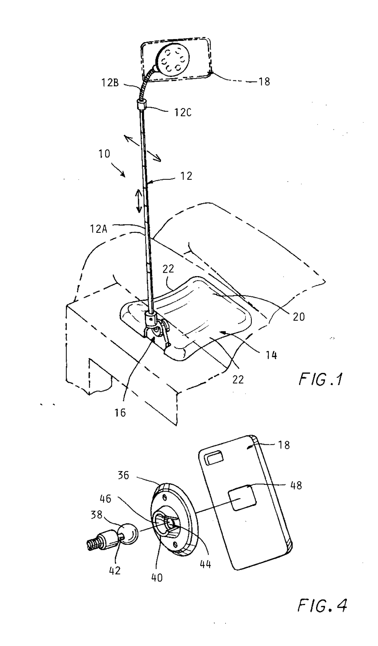
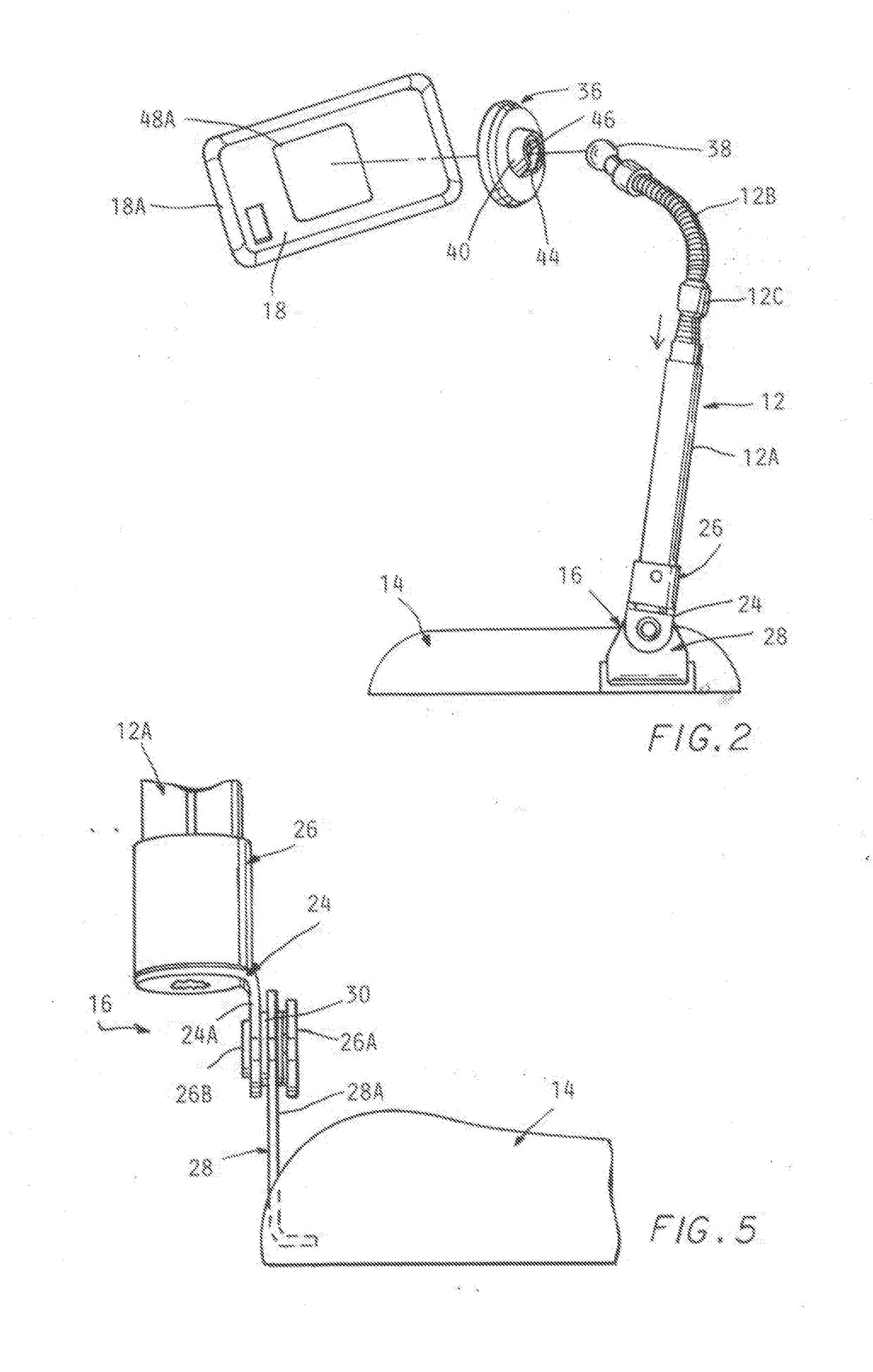
[0029]Referring to the drawings and particularly FIG. 1, an elevating support 10 according to one embodiment of the invention is shown in use by a seated user. The support 10 includes an elongated upright member 12, connected to a base piece 14 by a pivotal connection 16 to one side of the base piece 14.

[0030]The pivotal connection 16 allows the upright member 12 to be swung in a plane extending alongside the user or away from the user to obtain a desired location of an electronic device 18, shown in broken lines held adjacent the upper end of the upright member 12.

[0031...


PUM


Abstract

An adjustable support for holding an electronic device having a display at a desired elevated position for viewing of the display without tilting of the user's head. The support includes an upright elongated member pivotally connected to a generally planar base piece held beneath the user's thigh so as to hold the pivotally connected elongated member in an upright position. A telescoping and gooseneck segment enhance the adjustability of the position of the upright member at level and orientation enabling easy viewing of the display without tipping the head of a seated or reclining user. A magnetic or clamping cradle adjacent an upper end of the upright member by a ball joint engages the electronic device, with the ball joint providing adjustment of the orientation of the electronic device.

Description

CROSS REFERENCE TO RELATED APPLICATIONS[0001]This application claims the benefit of U.S. provisional application No. 62 / 222,291 filed on Sep. 23, 2015.BACKGROUND OF THE INVENTION[0002]This invention concerns a support for hand held electronic devices which have display screens for viewing text, drawings, photos, movies, etc., such as smart phones and tablets.[0003]The usual way for viewing such devices is to hold the device positioned in the vicinity of the person's lap or waist so that the person must tilt his or her head downwardly to view the display screen and any keyboard provided.[0004]Commonly, such position is assumed by the user for long periods of time.[0005]Sustained tilted neck positioning causes undesirable stress on one's spine particularly in the upper part thereof. The human head has a significant weight when compared to the load capacity of the spine. In a standing or seated position with the spine near vertical, the human spine is designed to best support the head ...

Claims


Application Information

Patent Timeline
Patent Type & Authority Applications(United States)
IPC IPC(8): H05K5/02F16M11/20F16M11/28F16B2/06F16M11/40F16M11/04F16B1/00A47B23/00F16B7/14
CPCH05K5/0204A47B23/007F16M11/2021F16M11/28F16B7/14F16B2001/0035F16M11/041F16B1/00F16M11/2078F16B2/06H05K5/0217F16M11/40A47B23/043F16M13/022F16M13/04F16M2200/022F16B2200/83F16M13/00
Inventor SIMON, DAVID F.
Owner SIMON DAVID F
Learn More