Eureka AIR delivers breakthrough ideas for toughest innovation challenges, trusted by R&D personnel around the world.

Method for deburring a gear blank

a gear blank and gear technology, applied in the direction of instrumentation, electric programme control, program control, etc., can solve the problems of non-uniform effect of vertical zsub>1/sub>-correction between the left and right tooth edges, and the correction of the setting data is difficult to achiev

Active Publication Date: 2017-03-30
LIEBHERR VERZAHNTECHNIK GMBH
View PDF7 Cites 3 Cited by
  • Summary
  • Abstract
  • Description
  • Claims
  • Application Information

AI Technical Summary

Benefits of technology

The present invention provides a method for determining the correction values for influencing the chamfer size, chamfer shape, and chamfer symmetry based on measured or entered data. By adjusting the settings of the gear cutting machine accordingly, a correct chamfer shape and appropriate size, as well as chamfer symmetry, can be achieved during the chamfering and deburring operation.

Problems solved by technology

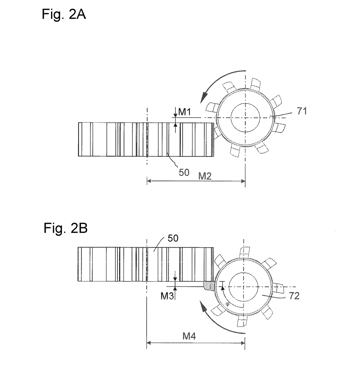
This particularity in the setting of the tool and in the chamfer production of a ChamferCut milling cutter leads to the fact that most of the parameters for the description of the ChamferCut milling cutter are only calculated mathematically, and cannot be measured at the milling cutter.
Since a plurality of axes is involved in the chamfer production, the correct setting sometimes turns out to be very difficult.
When chamfering and deburring helical toothings, it is particularly difficult that corrections of the setting data have different effects between the sharp and the obtuse tooth edge.
In helical toothings, however, this purely vertical Z1-correction has a non-uniform effect between the left and right tooth edges.
According to the prior art, the indications as to the chamfer size usually are provided on the finished part drawing and hence are not available for soft machining.

Method used


Image

  • Method for deburring a gear blank
  • Method for deburring a gear blank
  • Method for deburring a gear blank

Examples


Embodiment Construction

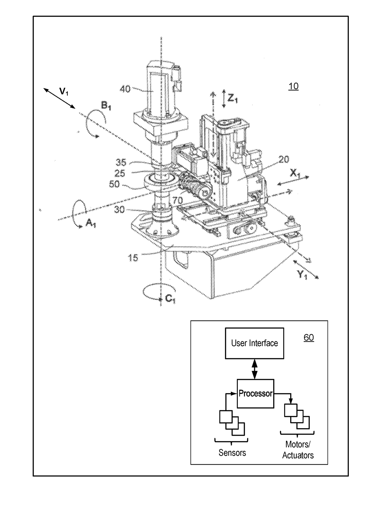
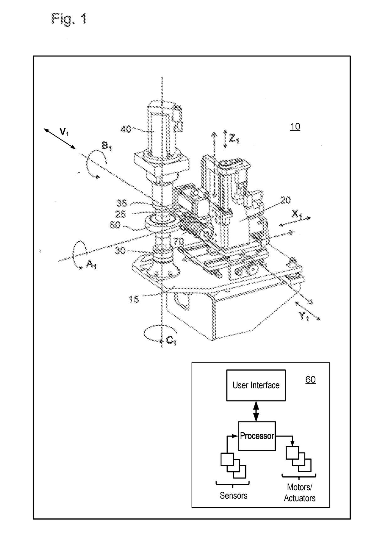
[0034]FIG. 1 shows an exemplary apparatus 10 for applying the method according to the present disclosure. The workpiece 50 to be machined is clamped between a workpiece support 30 and an upper clamping top 35. The workpiece is driven around the C1-axis via a drive 40. The tool axis B1 rotates relative to this C1-axis in a rollingly coupled manner and thereby drives the tool arbor 74. This tool arbor is accommodated in the machining head 25 which can be pivoted about the A1-axis and which is arranged on a machine column 20, in order to adjust the position of the tool in accordance with the helix angle of the toothing and the pitch angle of the tool. The feed movement of the tool is effected along the X1-axis and the Z1-axis with which the milling position below or above the toothing can be approached. Via the Y1-axis, the tools can be shifted tangentially to the workpiece. With these axes, the necessary correction movements according to this method also are effected in part, in that ...


PUM

PropertyMeasurementUnit
sizesaaaaaaaaaa
helix angleaaaaaaaaaa
swivel angleaaaaaaaaaa

Abstract

A method for deburring a gear blank includes correcting chamfer sizes, chamfer shapes and chamfer symmetry at tooth edges which were produced with a deburring cutter with a strongly asymmetric tooth shape (ChamferCut). The chamfers are semi-automatically corrected by coupling the movement of several axes of a gear cutting machine, including a workpiece axis of rotation C1, spatial shifting axes of a machine column Z1, X1, and Y1, and a V1-axis corresponding to the tool axis. The method further includes specifying a correction in the axial direction in one of the axes Z1, V1 and C1, and calculating the correction amount of further axes by the controller depending on the specified axis.

Description

CROSS REFERENCE TO RELATED APPLICATIONS[0001]This application claims priority to German Patent Application No. 10 2015 012 603.2, entitled “Method for Deburring a Gear Blank,” filed Sep. 28, 2015, the entire contents of which are hereby incorporated by reference in its entirety for all purposes.TECHNICAL FIELD[0002]This present disclosure relates to a method for deburring a gear blank and in particular to a method for the correction of chamfer sizes, chamfer shapes and chamfer symmetry at tooth edges which were produced with a deburring cutter with strongly asymmetric tooth shape (ChamferCut).BACKGROUND AND SUMMARY[0003]A ChamferCut milling cutter (alternatively referred to herein as a ChamferCut tool, milling tool, or milling cutter) is a forming cutter which has a strongly asymmetric profile and which in a continuous form milling process produces chamfers at the tooth edges of a toothed workpiece. The milling cutter furthermore is characterized by a high number of starts. In contr...

Claims


Application Information

Patent Timeline
Patent Type & Authority Applications(United States)
IPC IPC(8): B23F19/10G05B19/18B23F23/12
CPCB23F19/102B23F23/12G05B2219/45151G05B2219/36198G05B19/186B23F19/00B23F23/00B23Q17/2233B23F19/10B23F5/20B23Q17/22B23Q15/02
Inventor WINKEL, OLIVER
Owner LIEBHERR VERZAHNTECHNIK GMBH
Why Eureka
Eureka Blog
Learn More