Wheel with suspension system

a technology of suspension system and wheel, which is applied in the direction of wheelchair/patient conveyance, transportation and packaging, ambulance service, etc., can solve the problems of uneven rotation of the wheel, different damping characteristics of compressing the damper, and the wheel may break, so as to increase the overall stability and/or strength of the entire construction, the effect of increasing the stroke length of the support member and the inner spring elemen

Inactive Publication Date: 2017-03-30
SOFTWHEEL
View PDF9 Cites 22 Cited by
  • Summary
  • Abstract
  • Description
  • Claims
  • Application Information

AI Technical Summary

Benefits of technology

[0011]Therefore, it is one object of the invention to provide a wheel, particularly a wheel for self-propelled vehicle such as a wheel chair or a bicycle, having a smooth and even damping system.
[0014]A wheel according to the invention is connected or connectable to a vehicle, particularly to a self-propelled vehicle, a wheel chair or the like, or to other vehicles like cars, motorbikes etc. The wheel has a hub comprising an axle or being connectable to an axle. This hub may comprise a bearing, whereby particularly an inner ring of the bearing can be connected to the axle. Furthermore, the wheel comprises a rim being rotatable around the axle. The rim may particularly comprise a wheel rim, a tire, a hub, a bearing outer ring etc. Between the hub and the rim, at least one, particularly a plurality of support members, are located. The support members are normally providing a fixed distance between the station member and the rim. According to the invention, the support member is adapted to retain this distance when stressed up to a threshold value and to recoverably alter this distance when stressed over this threshold value. According to embodiments of the invention, this function of the support member is derived by a spring member, being part of the support member or building the support member. The spring member stores mechanical energy at compression, and in a preferred exemplary embodiment, the spring member is preloaded to a predetermined threshold value, thereby compresses only to compressive forces greater than the threshold value. In some embodiments, the spring member includes or is coupled or otherwise functionally linked to a damper, that is effectively operable (e. g., absorbs or dissipates kinetic energy) only during spring member change of size, or optionally only during its compression. In some embodiments, the spring member is in both ways compressed by the stroke, if the support member compresses and if it elongates. By compressing the spring member independent of compressing or elongating the support member, an identical dampening characteristic is optionally given. Therefore, the present invention has the advantage that particularly a wheel having a number of support members being located between the hub and the rim, can be smoothly damped, preferably only at strokes or shocks in a magnitude above a predetermined threshold value. Within a preferred embodiment of the invention, the supporting member comprises two longitudinal elements being slidably connected to each other. The two longitudinal elements are optionally comprising two cylinders, or a cylinder and a rod, one located inside the other. The spring element and / or damper can be located in and / or between the two longitudinal elements so that a relative movement of the longitudinal elements to each other causes the spring element and / or damper to be compressed.
[0018]Furthermore, the plurality of supporting members is optionally connected to the hub in a non-radial manner. Therefore, a compression force caused by an impact to a lower located supporting member of a wheel will not be transferred directly to the axle of the wheel, but at least partly guided surround the axle of the wheel causing an elongation of a support member being located in an upper position. Such a non-radial configuration has several advantages, including increased stroke length of the support member and inner spring element and / or damper and increase in overall stability and / or strength of the entire construction. Furthermore, when the hub shifts away from concentricity with respect to the rim and the suspension is activated, the non-radial configuration of the interconnecting supporting members causes the hub also to rotate about its axis with respect to the rim, so that particularly a piston type spring element and / or damper will avoid potential “sticking” phenomena, for example if the altering force is orthogonal thereto at the stroke initiation.

Problems solved by technology

This wheel has the possible drawback that due to the high stress of the spokes, the spokes may break.
The possible drawback of the use of such dampers is that the damping characteristics by compressing the damper differ from the damping characteristics by elongating the damper.
Due to the different damping characteristics, the rotation of the wheel becomes uneven.
Furthermore, the dampers described in DE 10 2005 032 537 cannot be preloaded.

Method used


Image

  • Wheel with suspension system
  • Wheel with suspension system
  • Wheel with suspension system

Examples


Embodiment Construction

[0033]The following preferred embodiments may be described in the context of exemplary suspension mechanisms for wheelchairs, or other types of self-propelled vehicles, for ease of description and understanding. However, the invention is not limited to the specifically described devices, and may be adapted to various applications without departing from the overall scope of the invention. For example, devices including concepts described herein may be used for suspension of any rotatable mass including wheels of motorized or otherwise powered vehicles.

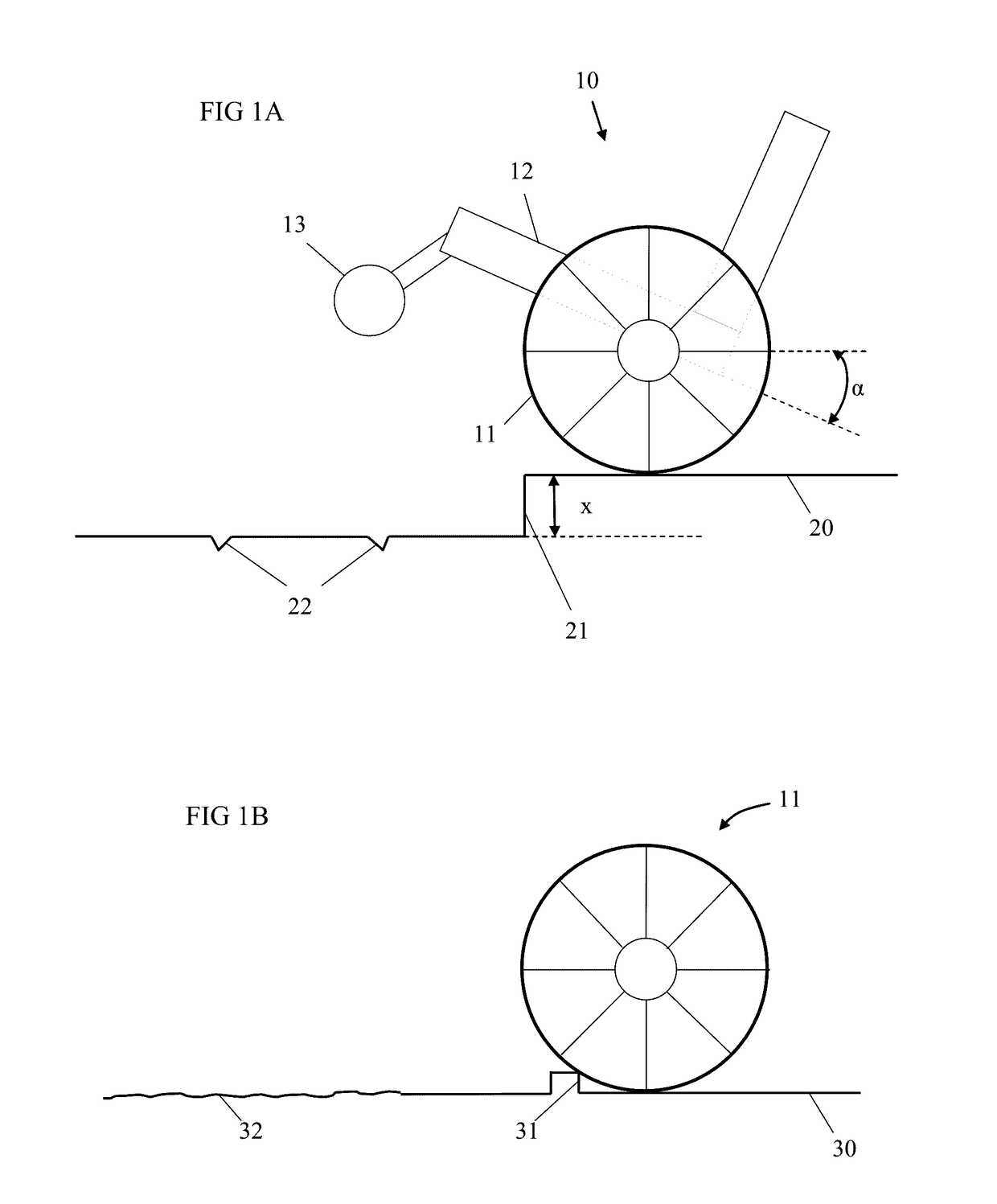
[0034]Common suspension systems are built to absorb interruptions and obstacles which cause deceleration and / or undesired vibration to the vehicle and / or aid the wheel in following the terrain and avoiding loss of contact with it, or grip. In doing so, the suspension systems are built to absorb and / or dissipate energy, including such that can be translated to effective kinetic energy. Furthermore, the common suspension systems (which in...


PUM


Abstract

A wheel with a suspension system being connectable to a vehicle, like a wheel chair. The wheel includes a hub and a rim rotatable about the axle of the hub. Between the hub and the rim, a number of support members is located. The support members are adapted to retain the distance when stressed up to a threshold value and recoverly alter the distanced when stressed over this threshold value. Exemplary support members are spring elements, damping strokes by compression if the support member is compressed or elongated. The spring elements may be preloaded.

Description

RELATED APPLICATIONS[0001]This application is a Divisional of U.S. patent appl. Ser. No. 14 / 354,607, filed on Apr. 28, 2014, entitled: “Wheel With Suspension System And Centralizing Unit With Suspension System”, which is a National Phase of PCT Patent Application No. PCT / IB2012 / 001994 having International filing date of Oct. 8, 2012, which claims the benefit of priority under §119(e) of U.S. Provisional Patent Application No. 61 / 552,505, filed on Oct. 28, 2011.[0002]PCT Patent Application No. PCT / IB2012 / 001994 is also a Continuation-In-Part (CIP) of PCT Patent Application No. PCT / IB2012 / 000530 having International filing date of Mar. 20, 2012, which claims the benefit of priority under §119(e) of U.S. Provisional Patent Application No. 61 / 552,505 filed on Oct. 28, 2011 and of U.S. Provisional Patent Application No. 61 / 485,086 filed on May 11, 2011.[0003]The contents of all the above applications are incorporated by reference as if fully set forth herein in their entireties.FIELD AND...

Claims


Application Information

Patent Timeline
Patent Type & Authority Applications(United States)
IPC IPC(8): B60B9/26B60B9/24B60G15/12B60B9/06
CPCB60B2200/22B60B9/26B60B9/06B60G2300/24B60G15/12B60G2204/30B60B9/24A61G5/06A61G2203/30B60B9/005A61G2203/70A61G5/1078A61G5/1081B60B9/28B60B9/10B60B9/18B60B33/045B60B2900/131B60B9/02
Inventor WINSHTEIN, RONNYGROSS, AMICHAY HAIMBRAND, DVIRSARDES, AHISHAY
Owner SOFTWHEEL
Why Eureka
Try Eureka