
Ladder filter

Active Publication Date: 2017-03-30
MURATA MFG CO LTD
View PDF6 Cites 4 Cited by
  • Summary
  • Abstract
  • Description
  • Claims
  • Application Information

AI Technical Summary

Benefits of technology

The present invention provides a ladder filter that can reduce the influence of a transverse mode ripple without increasing the size of each resonator. This is achieved by providing a sufficient high acoustic velocity region in the second parallel arm resonator, which results in favorable resonance characteristics without providing a low acoustic velocity region. Additionally, the resonant frequency of the second parallel arm resonator is increased so as to be equal to or higher than the resonant frequency of the series arm resonator, which improves out-of-band attenuation characteristics. Furthermore, the invention causes a transverse mode ripple to be spaced away from the resonant frequency of the series arm resonator, which further improves out-of-band attenuation characteristics.

Problems solved by technology

However, only by utilizing the resonant frequencies and the anti-resonant frequencies of the series arm resonators and the parallel arm resonators, it is difficult to obtain sufficient out-of-band attenuation characteristics.
However, in such a structure, since the low acoustic velocity region has to be provided, there is a problem that the area of each elastic wave resonator increases.

Method used


Image

  • Ladder filter
  • Ladder filter
  • Ladder filter

Examples


Embodiment Construction

[0025]Hereinafter, the present invention will be clarified by describing specific preferred embodiments of the present invention with reference to the drawings.

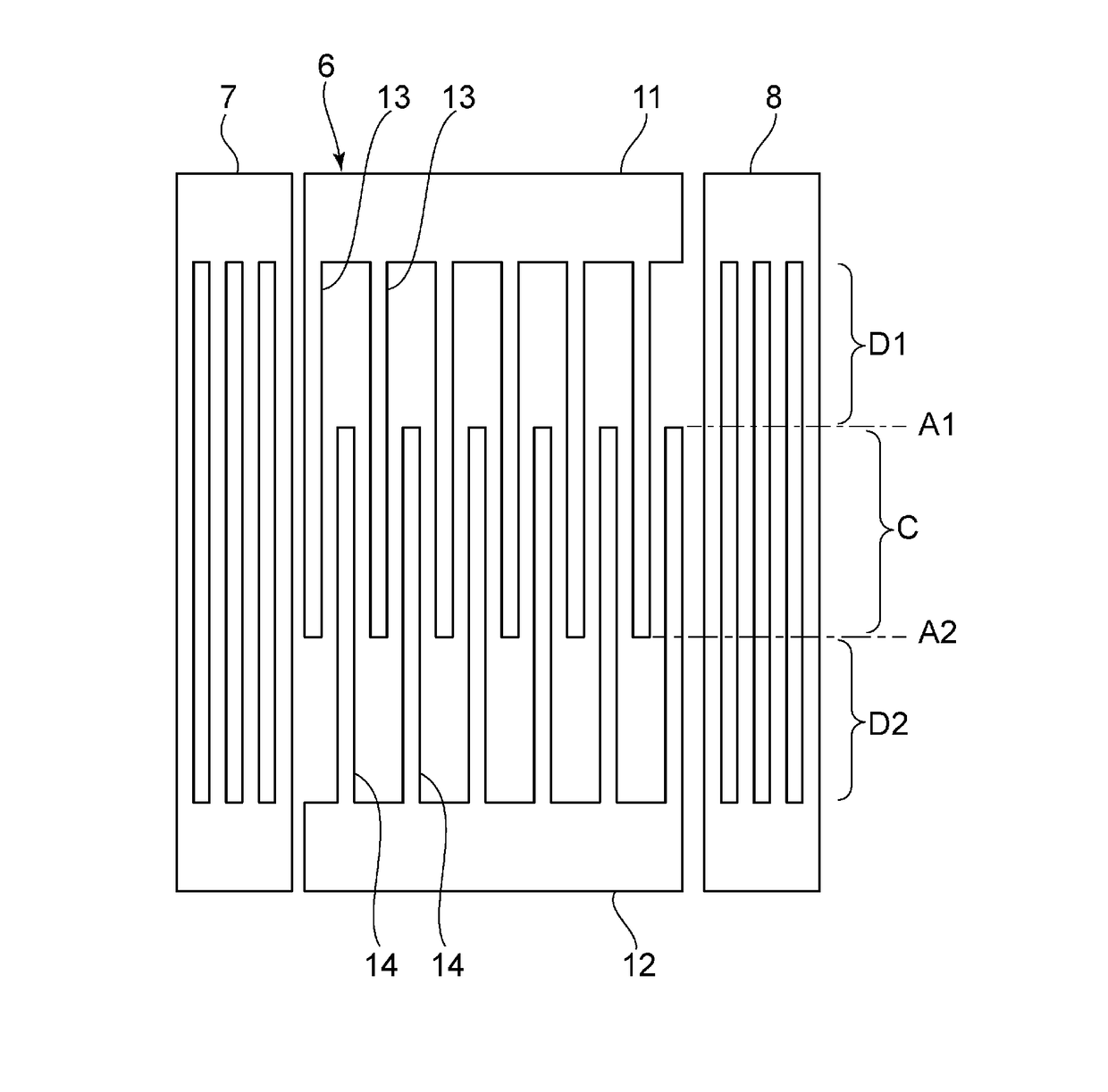
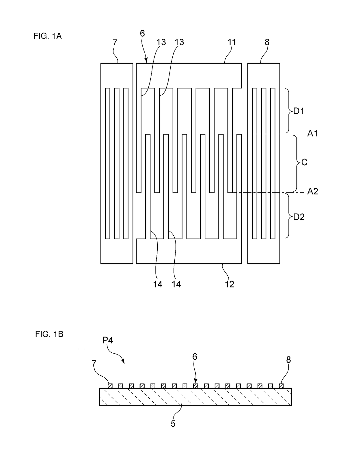
[0026]FIG. 4 is a circuit diagram of a ladder filter according to a first preferred embodiment of the present invention. The ladder filter 1 includes a series arm connecting an input terminal and an output terminal 3. In the series arm, series arm resonators S1 to S4 are connected in series. A plurality of parallel arms are provided to connect the series arm and a ground potential. Parallel arm resonators P1 to P4 are provided on the respective parallel arms. The parallel arm resonators P1 to P3 include a first parallel arm resonator, and define a pass band together with the series arm resonators S1 to S4. The parallel arm resonator P4 corresponds to a second parallel arm resonator.

[0027]The pass band of the ladder filter is provided by utilizing the resonance characteristics of the series arm resonators S1 to S4 and the reso...


PUM


Abstract

A ladder filter includes a series arm resonator and parallel arm resonators including a first parallel arm resonator defining a pass band together with the series arm resonator, and a second parallel arm resonator. Each of dimensions, in an overlap width direction, of gap regions between the overlap width region and first and second busbars in the second parallel arm resonator is larger than a dimension, in the overlap width direction, of a gap region in the first parallel arm resonator. A resonant frequency of the second parallel arm resonator is in a frequency range of not lower than a resonant frequency of the series arm resonator.

Description

CROSS REFERENCE TO RELATED APPLICATIONS[0001]This application claims the benefit of priority to Japanese Patent Application No. 2014-132654 filed on Jun. 27, 2014 and is a Continuation Application of PCT Application No. PCT / JP2015 / 062529 filed on Apr. 24, 2015. The entire contents of each application are hereby incorporated herein by reference.BACKGROUND OF THE INVENTION[0002]1. Field of the Invention[0003]The present invention relates to a ladder filter including a series arm resonator and a parallel arm resonator each including an elastic wave resonator.[0004]2. Description of the Related Art[0005]Hitherto, a ladder filter has been used as an RF-stage bandpass filter of a cellular phone or the like. The ladder filter includes a plurality of series arm resonators and a plurality of parallel arm resonators. An elastic wave resonator is generally used as each of the series arm resonators and the parallel arm resonators.[0006]Japanese Unexamined Patent Application Publication No. 2011...

Claims


Application Information

Patent Timeline
IPC IPC(8): H03H9/64H03H9/25H03H9/72
CPCH03H9/64H03H9/25H03H9/725H03H9/6483H03H9/145H03H9/1452H03H9/6423H03H9/6489
Inventor YOKOYAMA, JIN
Owner MURATA MFG CO LTD
Learn More