Subminiature internal antenna

Inactive Publication Date: 2009-02-05
EMW CO LTD
View PDF2 Cites 4 Cited by
  • Summary
  • Abstract
  • Description
  • Claims
  • Application Information

AI Technical Summary

Benefits of technology

[0012]As described above, the subminiature internal antenna according to the present invention has an excellent resonance characteristic at a multi-band and a broadband characteristic at a high-frequency band while occupying a much smaller installation space inside a co

Problems solved by technology

An external antenna such as a helical antenna or a whip antenna is protruded to the outside of the device, and hence has a high risk of damage.
In addition, the external antenna has high standing wave ratio so that the radiation characteristic of transmission power is deteriorated to thereby increase the amount of the electric power consumed due to power output control.
Also, the external antenna is not suitable for a trend toward miniaturization of the device since it is protrudingly mounted to the outside of the device.
Such an intern

Method used


Image

  • Subminiature internal antenna
  • Subminiature internal antenna
  • Subminiature internal antenna

Examples


Embodiment Construction

[0018]Reference will now be made in detail to a preferred embodiment of the present invention with reference to the attached drawings.

[0019]It will be understood by those skilled in the art that the embodiments described in the specification are merely exemplary and can be changed or modified into various different forms.

[0020]In the meantime, as used herein, the term “electric coupling” or “electrically coupled” refers to a state where two constituent elements are electrically connected to each other to allow electrons to be communicated as well as a state where two constituent elements are electromagnetically coupled to each other to induce current mutually although electrons are not allowed to be communicated.

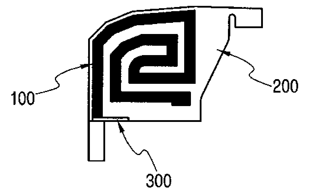
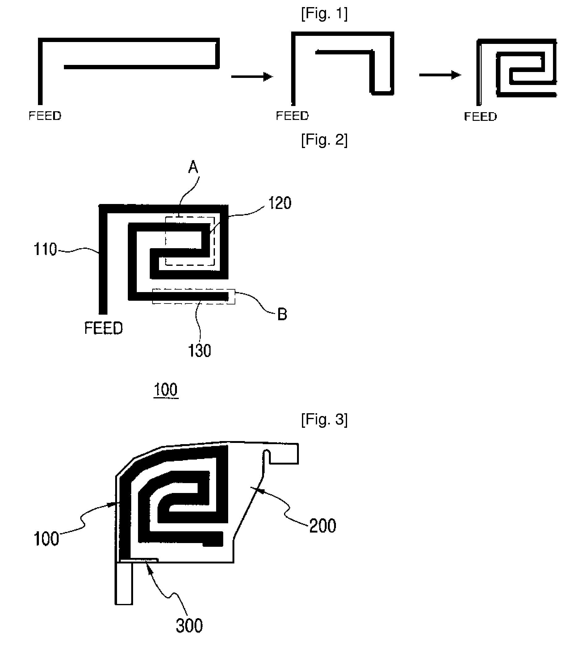
[0021]FIG. 1 is a schematic view illustrating a principle of forming a spiral radiator of a subminiature internal antenna according to one embodiment of the present invention. The spiral radiator of the internal antenna is formed based on a principle of a monopole antenna. T...


PUM


Abstract

Disclosed herein is a subminiature internal antenna, which exhibits a multi-band characteristic. The internal antenna includes a radiator electrically coupled at one end thereof to a feed element of a communication device and formed in a spiral shape as a whole. The radiator is disposed in such a manner as to extend at the other end thereof outwardly from the spiral shape. According to the present invention, the electromagnetic coupling is achieved in the radiator of the internal antenna and the other end of the radiator is disposed outwardly from the spiral shape so that the radiation interference is reduced to thereby obtain the multi-band characteristic.

Description

TECHNICAL FIELD[0001]The present invention relates to a subminiature internal antenna, and more particularly to, a subminiature internal antenna that is embedded in a mobile communication device.BACKGROUND ART[0002]An antenna of a mobile communication device is typically is subdivided into an external antenna exposedly mounted to the outside thereof and an internal antenna which is mounted to the inside thereof in terms of its installation position. An external antenna such as a helical antenna or a whip antenna is protruded to the outside of the device, and hence has a high risk of damage. In addition, the external antenna has high standing wave ratio so that the radiation characteristic of transmission power is deteriorated to thereby increase the amount of the electric power consumed due to power output control. Also, the external antenna is not suitable for a trend toward miniaturization of the device since it is protrudingly mounted to the outside of the device. Thus, currently...

Claims


Application Information

Patent Timeline
IPC IPC(8): H01Q9/27H01Q1/36
CPCH01Q1/36H01Q9/42H01Q9/27H01Q1/38
Inventor RYOU, BYUNG-HOONSUNG, WON-MOSEO, JEE-HUN
Owner EMW CO LTD
Why Eureka
Try Eureka