
Wavelength Optimization For Underwater Optical Communications

Active Publication Date: 2017-03-30
THE UNITED STATES OF AMERICA AS REPRESENTED BY THE SECRETARY OF THE NAVY
View PDF16 Cites 4 Cited by
  • Summary
  • Abstract
  • Description
  • Claims
  • Application Information

AI Technical Summary

Benefits of technology

The present invention is about a system and method for optimizing wavelengths for underwater optical communication. It includes multiple lasers with different wavelengths, a beam splitter, and a corner retro-reflector. The lasers and beam splitter are isolated from the environment, while the corner retro-reflector is placed in the environment. The lasers simultaneously illuminate the beam splitter along a coincident axis. The system also includes a means for selectively blocking one of the lasers so that only one laser at a time passes through the beam splitter. The process is repeated for each laser at different wavelengths until the minimum difference between the reference and return signals is reached, which is deemed as the optimum communication wavelength. The technical effect of this invention is to improve the efficiency and reliability of underwater optical communication by optimizing wavelengths for transmission.

Problems solved by technology

These devices are not known to be capable of lock-in techniques that enable sensitive detection, nor do they permit high-speed communication.
In other prior art systems, light that is backscattered from turbid seawater can be extinguished by using crossed polarizing optical elements, but the prior art systems of this type can only use one laser, and cannot adapt to changing environments.
A major drawback of this mirror-hole method is that some desired light may leak back through the initial hole, reducing the accuracy of the measurement.

Method used


Image

  • Wavelength Optimization For Underwater Optical Communications
  • Wavelength Optimization For Underwater Optical Communications
  • Wavelength Optimization For Underwater Optical Communications

Examples


Embodiment Construction

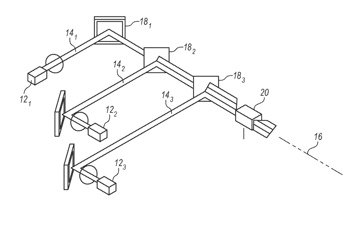
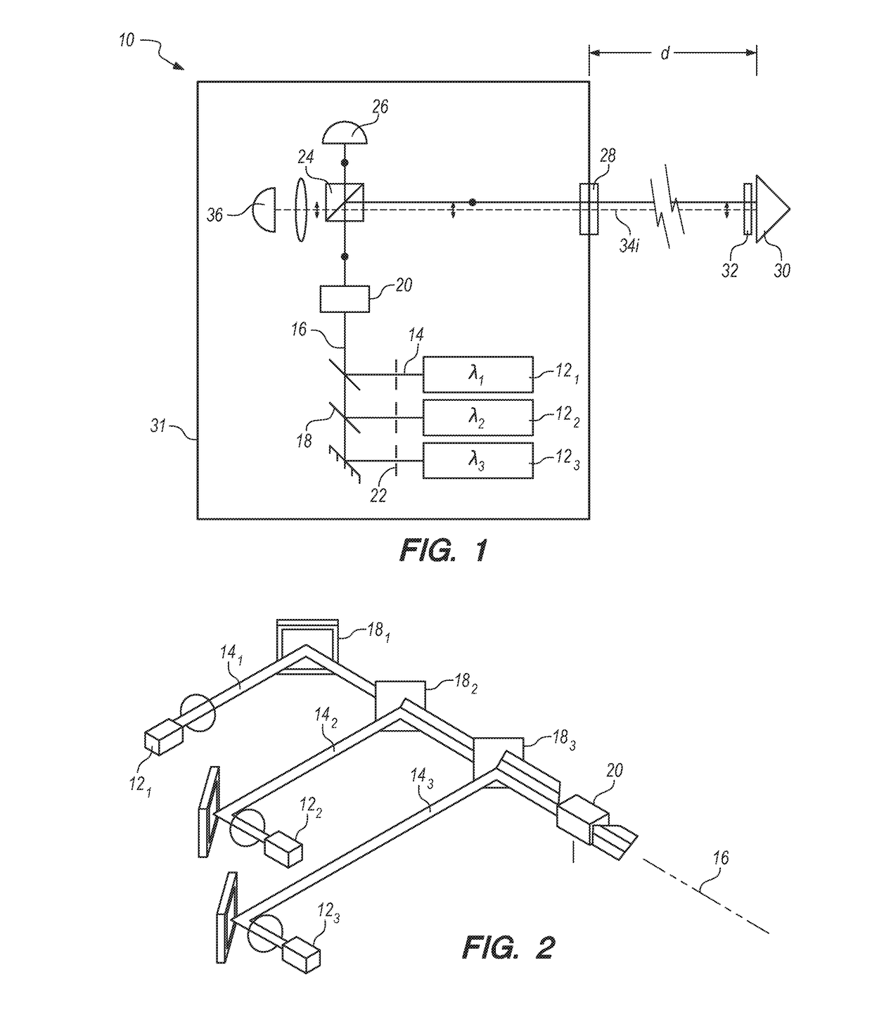
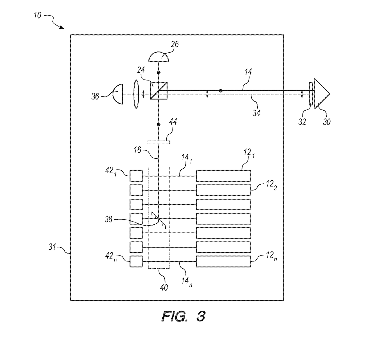
[0016]Referring initially to FIGS. 1-2, a system for environmental spectroscopy and wavelength optimization can be shown and can be generally designated by reference character 10. As shown, system 10 can include an array of n lasers 12i, of which representative lasers 121, 122 and 123 are shown in FIG. 1. Each laser 12i, can have a corresponding wavelength λi, which can be different from the other wavelengths λi for lasers 12. Wavelength λi can be in the blue-green portion of the visible spectrum (from approximately 475-550 nm) although other wavelengths are certainly possible for the present invention.

[0017]Each of the lasers 12 can generate a respective beam 14, as shown in FIG. 1. For the present invention, the plurality of lasers 12 can be manipulated to illuminate beams 14 along a coincident axis 16. To do this, the present invention according to several embodiments can include a plurality of dichroic mirrors 18, with each dichroic mirror corresponding to a respective laser 12 ...


PUM


Abstract

Systems and methods for wavelength optimization for underwater optical communication can include a plurality of n lasers having different wavelengths λi for i=1 to n, a beam splitter and a corner retro-reflector. The plurality of n lasers can simultaneously illuminate the beam splitter along a coincident axis. The plurality of n lasers can be selectively blocked so that only one laser wavelength λi at a time impinges on the beam splitter. A portion passes through the beam splitter to establish a reference signal, while the remainder is reflected off the corner retro-reflector. A portion of return illumination passes through the beam splitter to establish a return signal. The process can be repeated for each of n lasers for i=1 to n. The λi wavelength where the normalized signal-to-noise differential between the reference signal and return signal is the minimum can be the optimum communication wavelength.

Description

[0001]This application is a continuation-in-part of U.S. patent application Ser. No. 14 / 870,480, filed Sep. 30, 2015 by Burton H. Neuner III et al., for an invention entitled “Wavelength Optimization for Free-Space Optical Communications”. The '480 application is hereby incorporated by reference herein.FEDERALLY SPONSORED RESEARCH AND DEVELOPMENT[0002]The United States Government has ownership rights in this invention. Licensing inquiries may be directed to Office of Research and Technical Applications, Space and Naval Warfare Systems Center, Pacific, Code 72120, San Diego, Calif., 92152; telephone (619) 553-5118; email: ssc_pac_t2@navy.mil, referencing NC 103749.FIELD OF THE INVENTION[0003]The present invention pertains generally to spectroscopy systems and methods. More specifically, this invention pertains to spectroscopy systems that can combine multiple optical beams into a single beam, and that can continuously monitor the environment. The present invention is particularly, bu...

Claims


Application Information

Patent Timeline
IPC IPC(8): H04B10/80H01S3/00H04B10/50H01S3/23
CPCH04B10/80H04B10/503H01S3/0078H01S3/2391H04B13/02
Inventor NEUNER, III, BURTON H.HENING, ALEXANDRUPASCOGUIN, BIENVENIDO MELVIN
Owner THE UNITED STATES OF AMERICA AS REPRESENTED BY THE SECRETARY OF THE NAVY
Features
  • Generate Ideas
  • Intellectual Property
  • Life Sciences
  • Materials
  • Tech Scout
  • Unparalleled Data Quality
  • Higher Quality Content
  • 60% Fewer Hallucinations
Learn More