Supercharge Your Innovation With Domain-Expert AI Agents!

Methods and apparatus for a transmit path with frequency hopping phase locked loop

a phase lock loop and transmit path technology, applied in the field of wireless communication systems, can solve the problems of generating sems, affecting transmission on other channels, and frequency of carrier signals giving rise to spurious signal emissions,

Active Publication Date: 2017-03-30
QUALCOMM INC
View PDF6 Cites 4 Cited by
  • Summary
  • Abstract
  • Description
  • Claims
  • Application Information

AI Technical Summary

Benefits of technology

The patent describes an apparatus and method for frequency hopping uplink transmission. The apparatus includes a transmit path, multiple local oscillators, and a control unit. The control unit receives an upcoming resource block allocation and determines if it is the same as the current allocation. If the allocation is different, an unused local oscillator is selected, and the number of allocated resource blocks associated with the allocation is determined. If the number is not greater than a threshold, the selected local oscillator is tuned to the frequency of the allocation. The technical effect of this invention is to improve the efficiency and reliability of frequency hopping uplink transmission in wireless communication systems.

Problems solved by technology

Up-converting the modulating signal from the baseband to the frequency of the carrier signal may give rise to spurious signal emissions including for example, but not limited to, residual sideband (RSB) signals and intermodulation (IM) products (e.g., primary and second 4FMOD signals).
In particular, when RB allocation is narrow (e.g., one RB), the operation of a conventional transmit path may generate SEMs that fall outside of the frequency band allocated to a UE and interfere with transmissions on other channels.
However, adoption of AMPR parameters may reduce the output power of the UE and thus limit the UE's coverage area.

Method used


Image

  • Methods and apparatus for a transmit path with frequency hopping phase locked loop
  • Methods and apparatus for a transmit path with frequency hopping phase locked loop
  • Methods and apparatus for a transmit path with frequency hopping phase locked loop

Examples


Embodiment Construction

[0021]While a number of embodiments are described herein, these embodiments are presented by way of example only, and are not intended to limit the scope of protection. The apparatuses and methods described herein may be embodied in a variety of other forms. Furthermore, various omissions, substitutions, and changes in the form of the example apparatuses and methods described herein may be made without departing from the scope of protection.

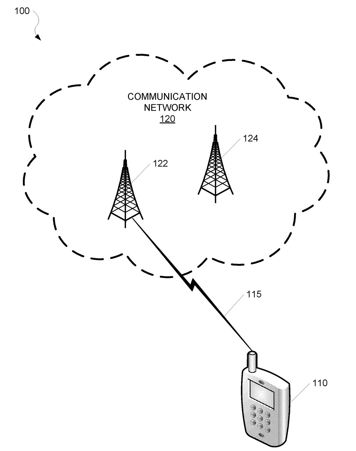
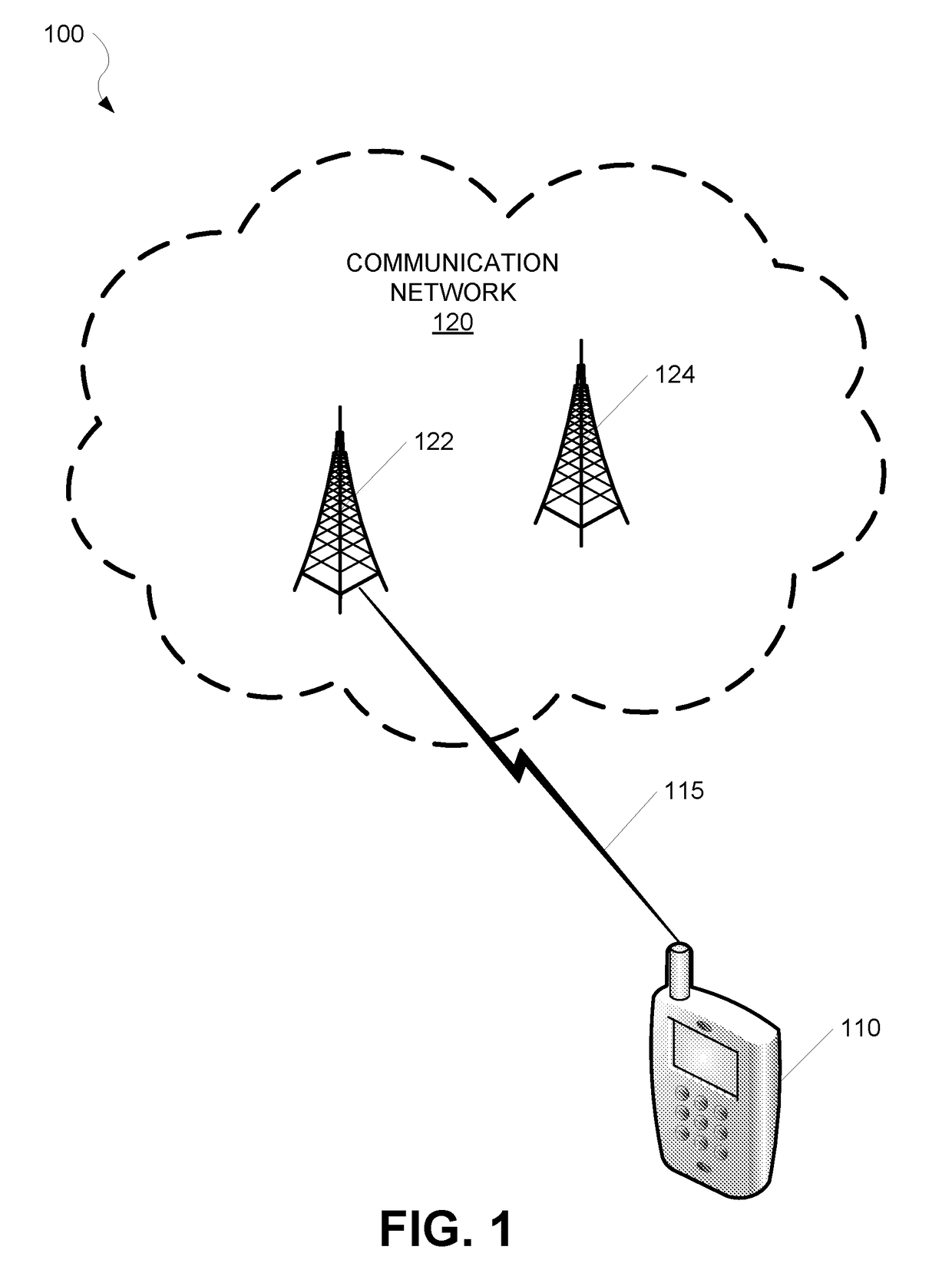
[0022]FIG. 1 is a system diagram illustrating a network environment 100 according to various embodiments. Referring to FIG. 1, a communication network 120 may include one or more Evolved Universal Mobile Telecommunications System (UMTS) Terrestrial Radio Access (E-UTRA) Node Bs (eNodeBs) including, for example, but not limited to, a first eNodeB 122 and a second eNodeB 124. The communication network 120 may be, for example, but not limited to, a wireless or mobile communication network.

[0023]The communication network 120 may be an LTE communicati...


PUM


Abstract

An apparatus comprising a transmit path, a plurality of local oscillators and a control unit. The control unit may be configured to: receive an upcoming resource block (RB) allocation; determine whether the upcoming RB allocation is the same as the current RB allocation; in response to determining that the upcoming RB allocation is different than the current RB allocation: select an unused LO of the plurality of LOs; determine whether a number of allocated RBs associated with the upcoming RB allocation is greater than a threshold; and in response to determining that the number of allocated RBs associated with the upcoming RB allocation is not greater than the threshold, tune the selected LO to a frequency corresponding to the upcoming RB allocation.

Description

CROSS-REFERENCE TO RELATED APPLICATIONS[0001]The present application is related to commonly owned Provisional Patent Application No. 62 / 233,180, Attorney Docket No. 152552P1, filed on Sep. 25, 2015, and entitled “Transmit Path with Frequency Hopping Phase Locked Loop,” which is incorporated herein by reference.BACKGROUND[0002]Technical Field[0003]The present disclosure relates generally to wireless communication systems, and more specifically to techniques for reducing spurious signal emissions.[0004]Related Art[0005]In a Long Term Evolution (LTE) communication network, uplink radio resources may be allocated dynamically to user equipment (UE) based on different application, data rates, and quality of service (QoS) requirements. Specifically, a UE in an LTE communication network may be allocated varying numbers of resource blocks (RBs) for uplink transmissions from the UE. Each RB may extend over one slot period (e.g., 0.5 milliseconds (ms)) in the time domain while occupying a cert...

Claims


Application Information

Patent Timeline
IPC IPC(8): H04W72/04H04B1/713
CPCH04B1/713H04W72/04H04B2001/71362H04L5/0044H04L5/0053H04L5/0094
Inventor ASURI, BHUSHAN SHANTIZHUANG, JINGCHENGSAMPATH, PRAVEENPATEL, SHRENIKDUNWORTH, JEREMY DARRENLEUNG, LAI KANSAHOTA, GURKANWAL SINGHPARK, JONG MIN
Owner QUALCOMM INC
Features
  • R&D
  • Intellectual Property
  • Life Sciences
  • Materials
  • Tech Scout
  • Unparalleled Data Quality
  • Higher Quality Content
  • 60% Fewer Hallucinations
Learn More