Impact machine

a technology of impact machine and impact plate, which is applied in the direction of shock absorbers, portable percussive tools, springs/dampers, etc., can solve the problems of body injuries, hard surface finally breaking, fatigue, etc., and achieve the effect of improving machine efficiency and vast design freedom

Active Publication Date: 2017-04-06
SWEREA IVF
View PDF10 Cites 1 Cited by
  • Summary
  • Abstract
  • Description
  • Claims
  • Application Information

AI Technical Summary

Benefits of technology

[0114]The advantages include that the vibrations from the impact machine are dampened for a large working frequency range and the absence of a sudden vibration increase enables the vibration reduction arrangement to exclude a safety zone; as well as that many different elements may be applied, giving rise to a vast design freedom.
[0115]The force from the counterweight on the housing also creates a feed force that improves the efficiency of the machine.

Problems solved by technology

In operation, fatigue in a hard surface may be achieved by applying a continuous impact force from the work tool, such that the hard surface finally breaks.
The vibrations may thus result in body injuries if the tool is hand-held and in machine wear if the tool is attached to a machine.
However, the arrangement in DE102009046348 does not provide any means for extending the dampened frequencies range of the machine tool.
However, still with this heavy weight, the machine generated very high vibrations in the range around region of 20 m / s2, hand arm weighted acceleration.
But when he was about to connect a counterweight to the housing of the impact machine by means of one spring at each end of the counterweight he realized that he did not have sufficiently strong springs at home to get the right working frequency.
As predicted, the dampening arrangement did not work at all when he turned the machine on.
The machine just bounced around, being extremely difficult to control.
There was no reasonable explanation to this.
When he later disassembled the machine, he could see nothing unordinary except that the force of the counterweight had compressed the springs, such that there were gaps between the counterweight and the springs.
A movement beyond these points is thus not possible, or normally not possible, when the machine is operated at rated power.

Method used


Image

  • Impact machine
  • Impact machine
  • Impact machine

Examples


embodiment 1

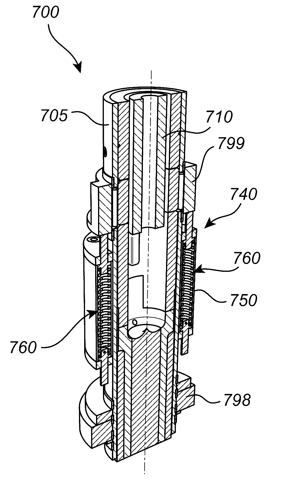
[0254]An impact machine (100; 200) comprising:

[0255]a housing (105; 205)

[0256]a hammering element (110; 210) arranged inside said housing (105; 205), said hammering element (110; 210) is displaceable between a first hammering element position (H1) and a second hammering element position (H2),

[0257]an impact receiving element (130; 230) attached to said housing (105; 205),

[0258]actuating means (115; 215) arranged to cause said hammering element (110; 210) to perform a hammering operation on said impact receiving element (130; 230),

[0259]a vibration reduction arrangement (140; 240) attached to said housing (105; 205), which comprises:[0260]a counterweight (150; 250) being displaceable in a first axial direction (A) between a first counterweight position (CW1) and a second counterweight position (CW2) in response to the hammering action of said hammering element (110; 210),[0261]at least one motion reversing mechanism (180; 280) each of said motion reversion mechanism comprising at lea...

embodiment 2

[0265]The impact machine according to embodiment 1, wherein said counterweight (550) is arrangeable at a position located between said first counterweight position (CW1) and said second counterweight position (CW2) from which position said counterweight (550) is moveable a first distance (D1) extending in said first axial direction (A) without actuating said at least one spring-action arrangement (160) and said at least one spring action arrangement (560) being arranged inside said counterweight (550), and said vibration reduction arrangement further comprises:

[0266]a first end surface (SEnd1) arranged adjacent to said first counterweight position (CW1) and

[0267]a second end surface (SEnd2) arranged adjacent to said second counterweight position (CW2);

said first end surface (SEnd1) is arranged to receive said at least one spring action arrangement (560) when in motion towards said first counterweight position (CW1); and

said second end surface (SEnd2) is arranged to receive said at l...

embodiment 3

[0268]The impact machine according to embodiment 2, wherein said at least one spring action arrangement (560) comprises a first spring action member, which first spring action member is prestressed, said first spring action member having a first spring characteristics (k1) within the interval ktrad / 5≦k1≦30*ktrad.


PUM


Abstract

The invention relates to an impact machine which is adapted to perform a hammering operation on a surface or an object to be worked upon. In particular, a vibration reduction arrangement is attached to the housing and comprises a moveable counterweight, interacting with a motion reversing arrangement having a non-linear spring characteristics, such that the motion of the counterweight can be brought into a counter-acting movement in relation to the vibrations in the housing of the hammering element thus substantially reducing the vibrations. A spring action arrangement is arranged inside said counter weight, the counter weight being movable a first distance without actuating the spring action arrangement, and the counterweight comprises displaceable projecting member for actuating the spring action arrangement.

Description

FIELD OF THE INVENTION[0001]The present invention relates to the field of impact machines, and more specifically to impact machines comprising a vibration reduction arrangement.BACKGROUND AND SUMMARY OF THE INVENTION[0002]Impact machines are frequently used in quarries, road construction and building construction applications in order to work hard surfaces, such as rock, concrete and pavements or softer materials such as asphalt. The invention can be used on machines such as rock drills, breakers, rammers and hammers which all have a similar impact mechanism.[0003]A common design for impact machines comprises hydraulic, pneumatic, combustion engine or electrical actuating means and a moveable impact element transferring an impact force to a work tool attached to the housing. In operation, fatigue in a hard surface may be achieved by applying a continuous impact force from the work tool, such that the hard surface finally breaks. However, parts of the vibrations from the movements of...

Claims


Application Information

Patent Timeline
Patent Type & Authority Applications(United States)
IPC IPC(8): B25D17/24F16F7/116
CPCB25D17/24F16F7/116B25D2250/275B25D2250/245B25D2217/0092
Inventor LINDELL, HANS
Owner SWEREA IVF
Why Eureka
Try Eureka