Method and System of Scanner Automation for X-Ray Tube with 3D Camera

a technology of x-ray tube and scanner, applied in the direction of instruments, patient positioning for diagnostics, applications, etc., can solve the problem of inconsistency between different x-ray scans

Active Publication Date: 2017-04-13
SIEMENS HEALTHCARE GMBH
View PDF1 Cites 43 Cited by
  • Summary
  • Abstract
  • Description
  • Claims
  • Application Information

AI Technical Summary

Problems solved by technology

The positioning and orientation of the X-ray tube with respect to the patient relies on the t...

Method used


Image

  • Method and System of Scanner Automation for X-Ray Tube with 3D Camera
  • Method and System of Scanner Automation for X-Ray Tube with 3D Camera
  • Method and System of Scanner Automation for X-Ray Tube with 3D Camera

Examples


first embodiment

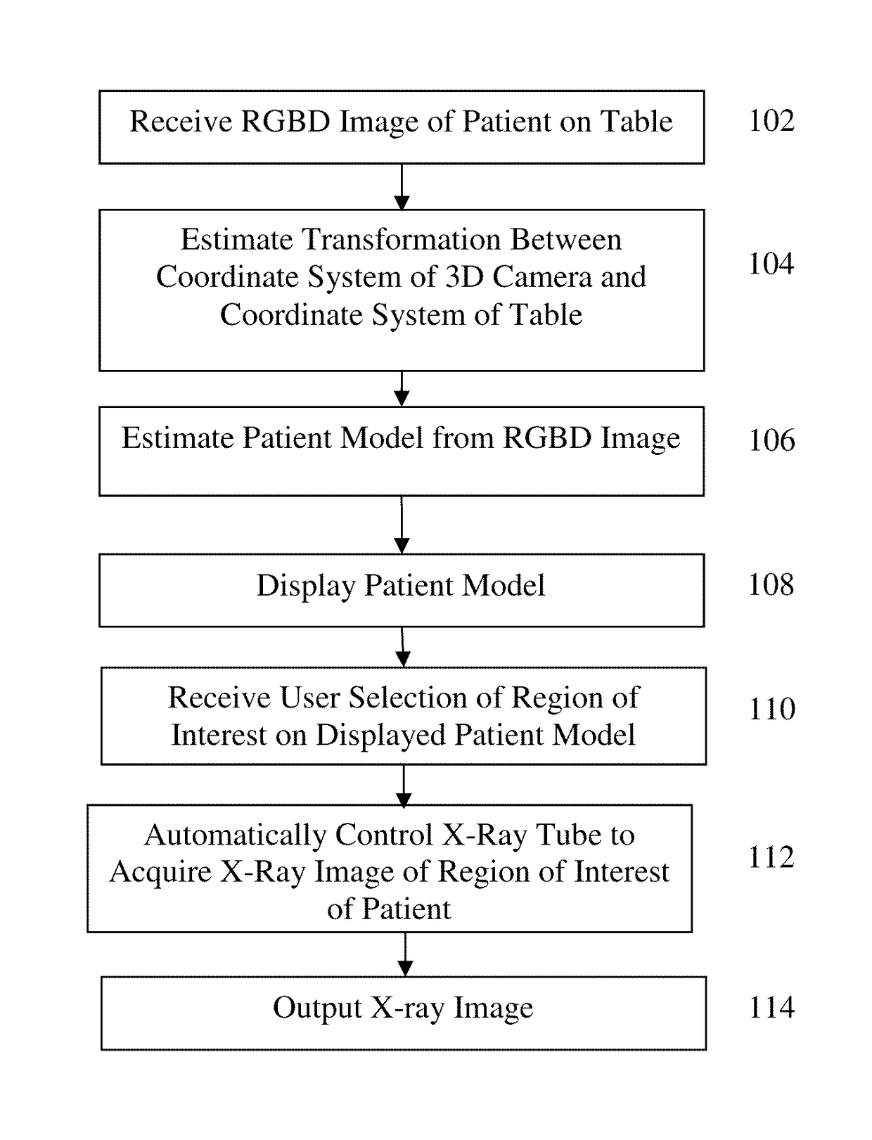
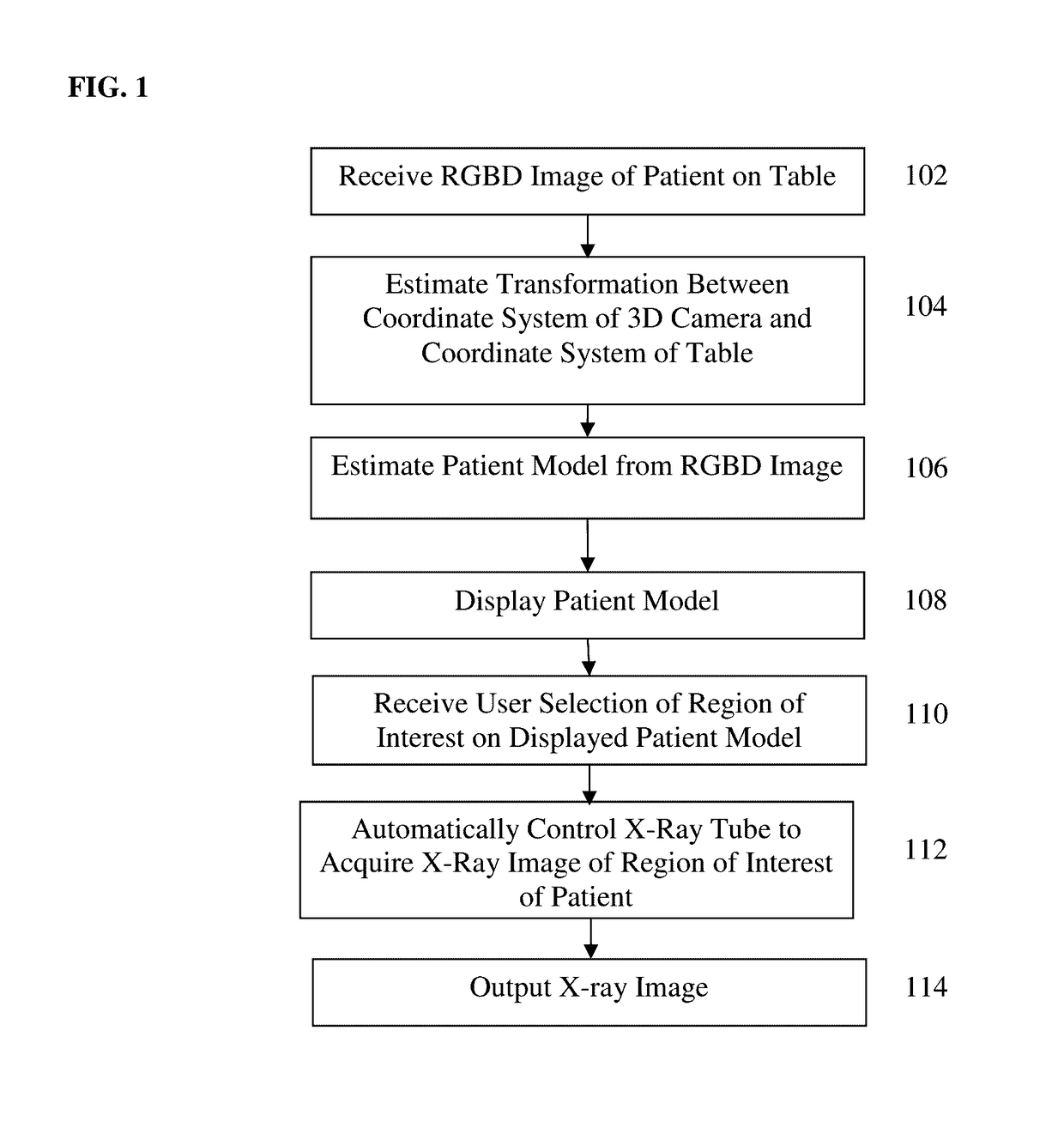
[0020]Returning to FIG. 1, at step 104, a transformation between a coordinate system of the 3D camera and a coordinate system of the patient table is calculated. In a first embodiment, the transformation between the coordinate system of the 3D camera and the coordinate system of the patient table is calculated by detecting table markers in the RGBD image and the estimating the transformation between the coordinate system of the 3D camera and the coordinate system of the patient table based on the detected table markers in the RGBD image. One challenge of mounting the 3D camera on the X-ray tube is that the 3D camera's position will not remain constant with respect to the patient table and the scanning room coordinate system. According to an advantageous embodiment of the present invention, by assuming that the patient table is at least partially visible in the 3D camera's field of view, the patient table is equipped with colored ring markers that are used for automatic registration ...

second embodiment

[0023]In a second embodiment, tube position control parameters of a control system of the X-ray tube are received, and the transformation between the coordinate system of the 3D camera and the coordinate system of the patient table is calculated using a kinematic calibration based on the tube position control parameters of the control system of the X-ray tube. This embodiment enables automated control of the X-ray tube without the need for detecting the table markers. In an exemplary implementation, the tube position control parameters (which are described in greater detail below in connection with FIG. 7) can include three translational parameters and two rotational parameters to control a position and orientation of the X-ray tube. The tube position control parameters corresponding to a current position and orientation of the X-ray tube can be received from the control system of the X-ray tube and used in the kinematic calibration. The kinematic calibration calibrates the coordina...


PUM


Abstract

A method and apparatus for X-ray tube scanner automation using a 3D camera is disclosed. An RGBD image of a patient on a patient table is received from a 3D camera mounted on an X-ray tube. A transformation between a coordinate system of the 3D camera and a coordinate system of the patient table is calculated. A patient model is estimated from the RGBD image of the patient. The X-ray tube is automatically controlled to acquire an X-ray image of a region of interest of the patient based on the patient model.

Description

BACKGROUND OF THE INVENTION[0001]The present invention relates to scanner automation for X-ray image acquisition, and more particularly, to X-ray tube scanner automation using a 3D camera.[0002]X-ray scanning in typically performed by a technician manually positioning an X-ray tube to focus the X-ray scan on a region of interest on a patient. The positioning and orientation of the X-ray tube with respect to the patient relies on the technician's subjective decisions, which often leads to inconsistency between different X-ray scans. X-ray scanner automation is desirable due to multiple potential benefits. In addition to improved efficiency of the scanning workflow, X-ray scanner automation may also provide better scan quality as compared with X-ray scans obtained by technicians manually positioning the X-ray tube.BRIEF SUMMARY OF THE INVENTION[0003]The present invention provides a method and system for X-ray tube scanner automatic using a 3D camera. Embodiments of the present inventi...

Claims


Application Information

Patent Timeline
IPC IPC(8): A61B6/00A61B6/04G16Z99/00
CPCA61B6/54A61B6/0492A61B6/582A61B6/461A61B6/469A61B6/488A61B6/00A61B6/4429A61B6/466A61B6/48A61B6/5205A61B6/5229G16Z99/00A61B6/4464A61B6/465A61B6/467A61B6/544A61B6/545G16H50/50
Inventor CHANG, YAO-JENSINGH, VIVEK KUMARMA, KAINANKE, RALFDORNBERGER, SUSANNECHEN, TERRENCE
Owner SIEMENS HEALTHCARE GMBH
Why Eureka
Try Eureka