Compound applicator

a technology of compound applicators and applicators, which is applied in the direction of coatings, constructions, buildings, etc., to achieve the effects of improving balance, facilitating application, and improving control of the applicator

Inactive Publication Date: 2017-04-13
INGERSOLL PROD
View PDF1 Cites 5 Cited by
  • Summary
  • Abstract
  • Description
  • Claims
  • Application Information

AI Technical Summary

Benefits of technology

[0014]The curvature of the blade is adjustably set by means of an interlocking slide mechanism which allows for the compound to be applied to the target surface in a controlled range of desired thicknesses as well as with the desired camber profile of the applied compound.
[0015]The blade has a series of projections along its length that shear through the pseudoplastic drywall compound, making it easier to apply in a controlled manner with a smooth surface free of voids or other flaws.
[0016]The attachment between the applicator head and the applicator reservoir allows for a range of single axis rotation between the head and reservoir, giving the user better control of the applicator while the semi-fluid material is being applied to the target surface.
[0017]A tubular reservoir carries the source material being applied to the wall joint in a manner that distributes the weight over its length, lending the tool better balance and making it easier to operate.
[0018]The attachment method is such that the applicator reservoir can be easily detached and reattached to the applicator head, or another applicator head without the use of tools to do so.

Problems solved by technology

These formations are difficult to clean after use and compound that is left to harden in these areas can later come loose while the tool is in use and mar the desired smooth appearance of the bead of compound being applied to the wall surface.

Method used


Image

  • Compound applicator
  • Compound applicator
  • Compound applicator

Examples


further embodiment

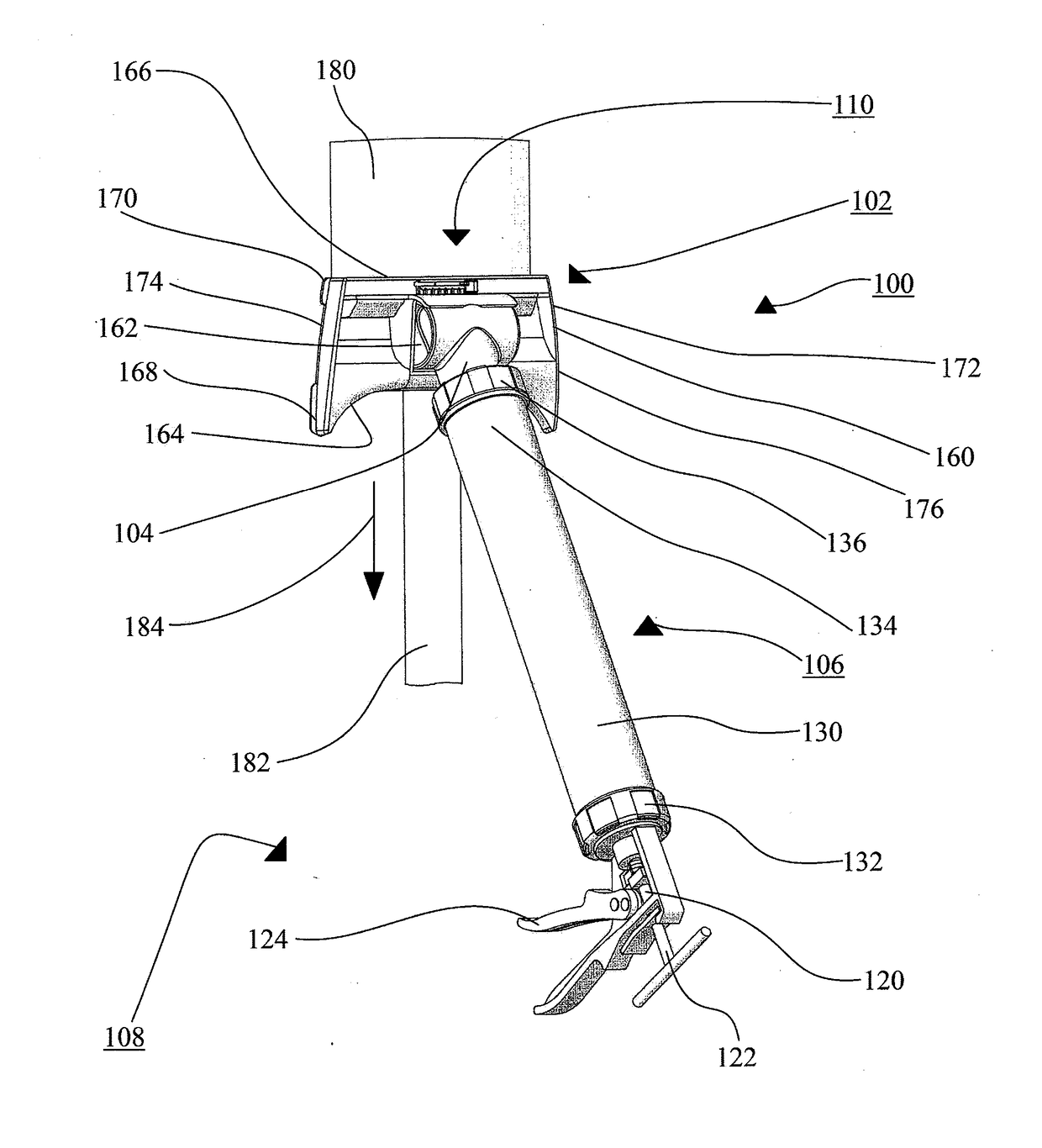
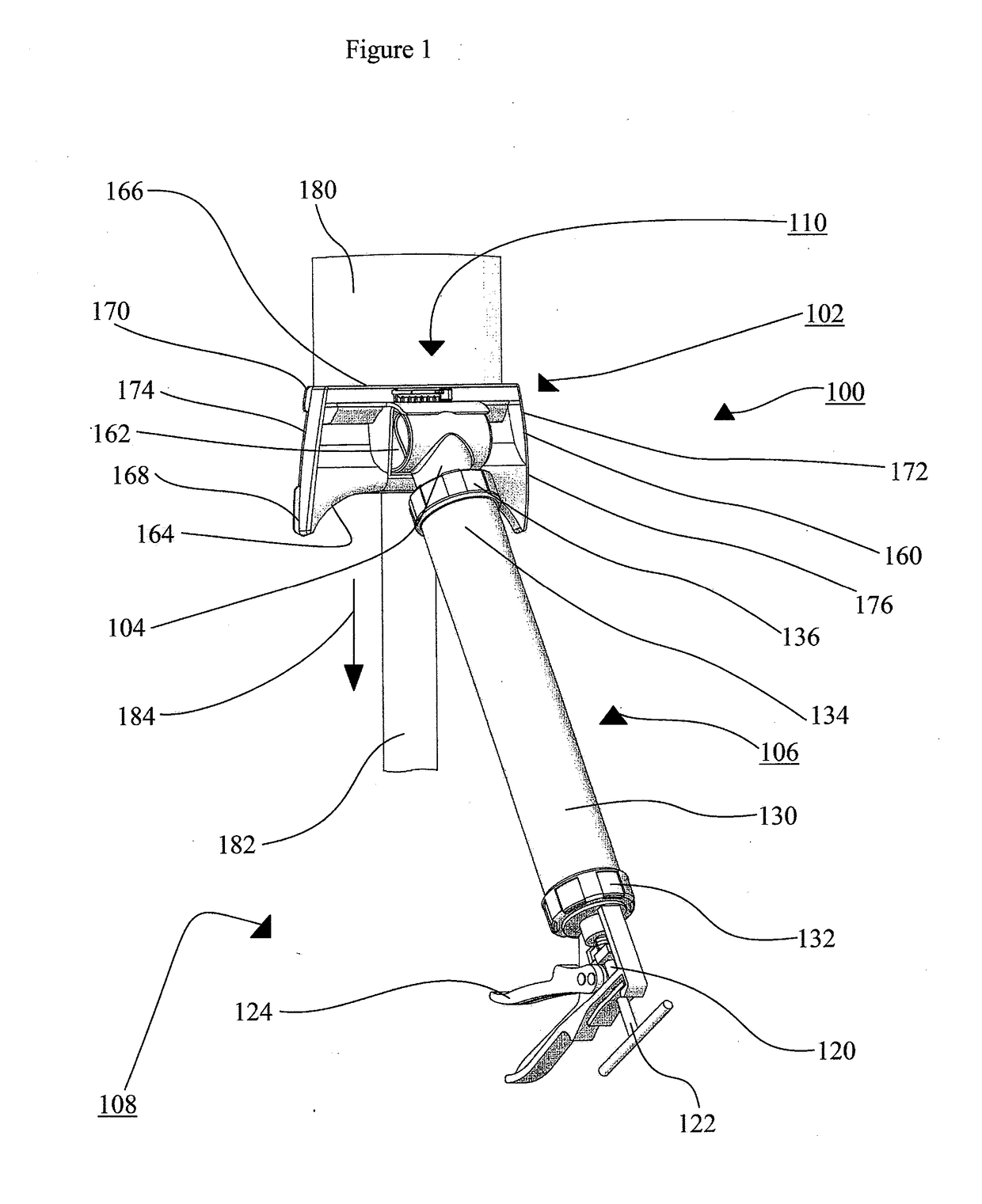
[0083]An alternate embodiment of the present concept is a compound applicator shown generally as 400 as shown in FIGS. 11.

[0084]Referring first to FIGS. 1 and 11, the major components of compound applicator 400 are as follows: applicator head 402 attached to an applicator reservoir 106 which in turns is attached to an applicator gun 108.

[0085]The major components of the applicator head 402 are as follows: pressure control connector 404, body 406, front skid 408, and adjustment mechanism 110.

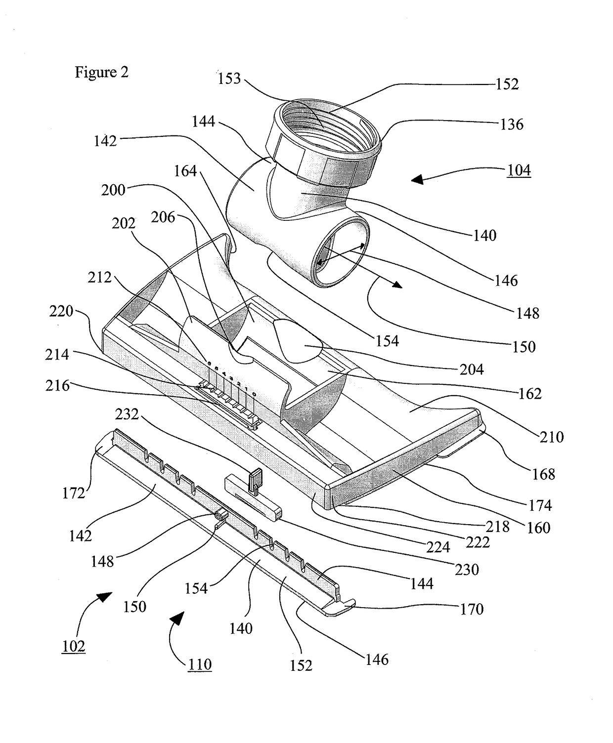
[0086]Referring specifically to FIG. 11 which show further details of the body 406 of applicator head 402. The reader will note that the body 406 shown in FIG. 11 is similar to body 160, shown in FIGS. 1 to 10, with minor modifications relating to the removability of the skids; namely, the left skid 170 and right skid 172.

[0087]The body 406 defines a socket 662 wherein the pressure control connector 404 snugly fits therein. The body 406 further includes leading edge 664, trailing edge 667, and sk...


PUM


Abstract

A compound applicator includes: an applicator head which includes a body for applying a bead of compound onto a surface, wherein the profile of the compound bead has a convex profile with a crown and bead thickness; a device for controlling the crown and bead thickness of the convex profile with an adjustment mechanism. The adjustment mechanism includes a blade which includes a horizontal portion and a vertical portion and wherein the distal ends of the horizontal portion of the blade abut against the body, such that the blade can be resiliently flexed between a highest cambered position and a low camber position by vertically displacing a central portion of the blade.

Description

[0001]The present application is a national stage entry of international application PCT / CA2015 / 050580 which claims priority from regularly filed U.S. provisional patent application 62 / 016,912 filed Jun. 25, 2014 under the title; COMPOUND APPLICATOR in the name of Jamie Pentland.FIELD OF THE INVENTION[0002]The present concept relates to compound applicators and more particularly relates to applicator heads used in conjunction with compound applicators.BACKGROUND OF THE INVENTION[0003]The compound applicator of the present design utilizes a molded applicator head which includes a smooth surface flow channel and a uni-body design.[0004]The molded uni-body design allows for the elimination of the formation of sharp internal corners, crevasses and raised obstructions within the compound flow channel that can be found in other similar tools that have machined surfaces and use multiple components and fasteners within their construction. These formations are difficult to clean after use an...

Claims


Application Information

Patent Timeline
Patent Type & Authority Applications(United States)
IPC IPC(8): B05C17/10E04F21/165B05C17/01B05C5/02B05C17/005
CPCB05C17/10B05C5/0262E04F21/165B05C17/0123B05C17/00516B05C17/01B05C5/0254E04F21/1652
Inventor PENTLAND, JAMIE
Owner INGERSOLL PROD
Why Eureka
Try Eureka