Image correction method and microscope

Inactive Publication Date: 2017-04-13
CARL ZEISS MICROSCOPY GMBH
View PDF9 Cites 0 Cited by
  • Summary
  • Abstract
  • Description
  • Claims
  • Application Information

AI Technical Summary

Benefits of technology

The invention is an image correction method and microscope that use parallel image processing to acquire and assign brightness value portions of an object location to adjacent pixels during image-capturing. This allows for high processing speed and the provision of brightness values or summary brightness value portions when the image-capturing process ends. The method also reduces latency times and allows for ideal actuation and guidance of the beam-directing element and scanning beam. Additionally, the method reduces influence of bidirectional imaging errors and compresses image data during the image-capturing process.

Problems solved by technology

If a beam-directing element, for example a mirror, is used for guiding the scanning beam over the object plane, it is possible, despite linear actuation and orientation of the beam-directing element, for a non-linear scanning path of the scanning beam in the object plane to occur, resulting in imaging errors in the form of geometric distortions.

Method used


Image

  • Image correction method and microscope
  • Image correction method and microscope
  • Image correction method and microscope

Examples


Embodiment Construction

[0056]It is to be understood that the figures and descriptions of the present invention have been simplified to illustrate elements that are relevant for a clear understanding of the present invention, while eliminating, for purposes of clarity, many other elements which are conventional in this art. Those of ordinary skill in the art will recognize that other elements are desirable for implementing the present invention. However, because such elements are well known in the art, and because they do not facilitate a better understanding of the present invention, a discussion of such elements is not provided herein.

[0057]The present invention will now be described in detail on the basis of exemplary embodiments.

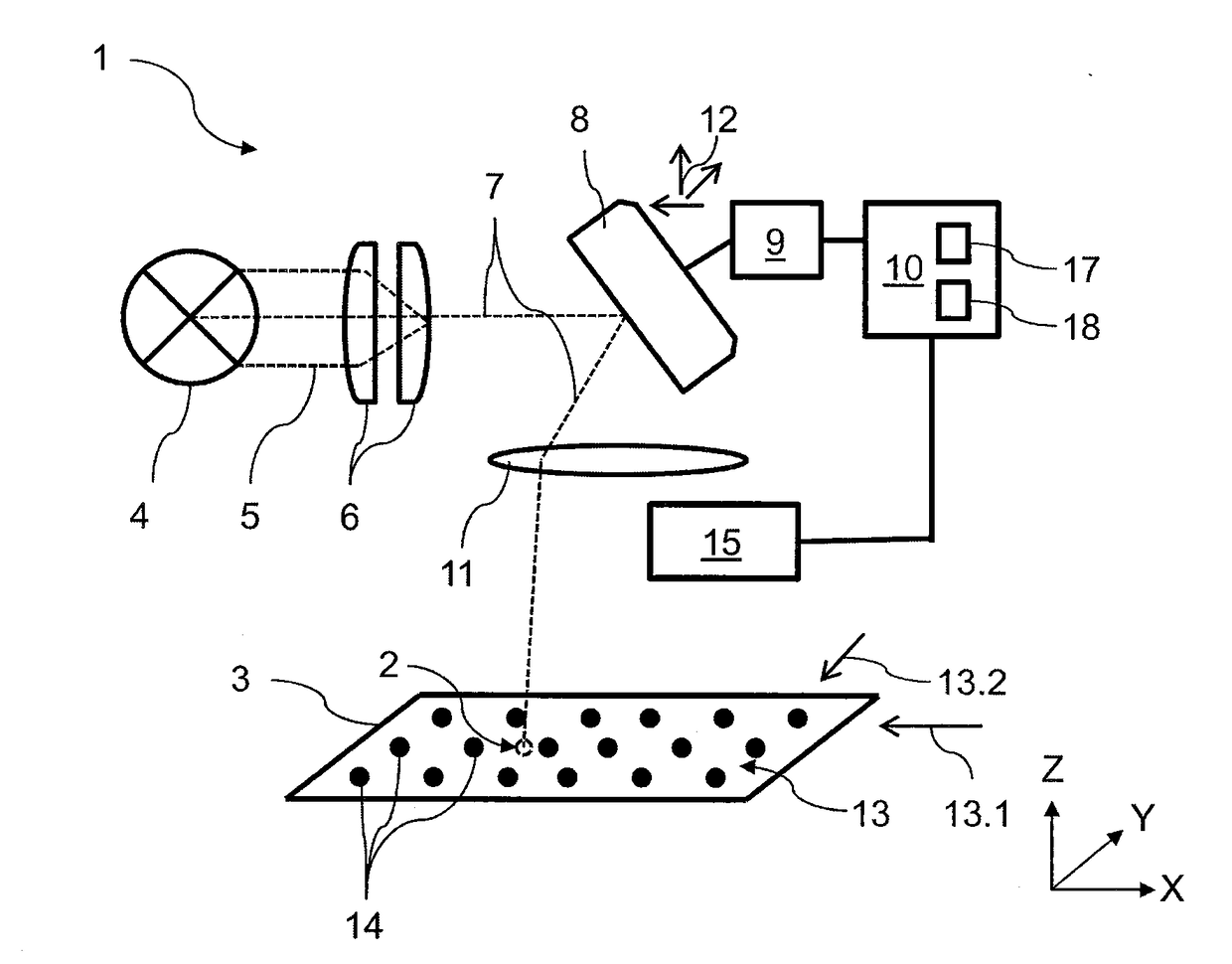
[0058]In FIG. 1 an exemplary embodiment of a microscope 1 is illustrated schematically, which microscope 1 is designed to detect brightness values at object locations 2 in an object plane 3. The microscope 1 has a radiation source 4 for making available electromagnetic radiatio...


PUM


Abstract

An image correction method is provided in which, in order to capture images, a scanning beam is guided over an object plane by a beam-directing element, and at detection times a brightness value of a detection signal of an object location scanned at the respective detection time is detected in the object plane, wherein actual positions of the beam-directing element and the positions of the object locations which are associated with the actual positions are known at every detection time. A pixel array with known positions of each pixel of the pixel array is defined in the object plane, a number of pixels adjacent to the object location is acquired, and the brightness value which is detected at an object location is assigned proportionally to the adjacent pixels of the object location as brightness value portions. Also provided is a microscope designed to carry out the image correction method.

Description

[0001]The present application claims priority from German Patent Application No. 10 2015 219 709.3 filed on Oct. 12, 2015, the disclosures of which are incorporated herein by reference in their entirety.FIELD OF THE INVENTION[0002]It is noted that citation or identification of any document in this application is not an admission that such document is available as prior art to the present invention.[0003]The invention relates to an image correction method for correcting imaging errors of an image-capturing process in which image data are detected by means of a scanning method, and to a microscope which is designed to carry out the method.[0004]When an image is captured using a scanning method, a scanning beam is guided, by means of at least one beam-directing element, over an object plane in which, for example, a sample which is to be imaged is located. The image data is acquired in the form of brightness values of object locations in the object plane or on the surface of the sample ...

Claims


Application Information

Patent Timeline
IPC IPC(8): G02B21/00H04N5/225G02B21/36H04N5/235
CPCG02B21/0084H04N5/2351G02B21/365G02B21/0048H04N5/2256H04N3/06H04N23/81H04N23/56H04N23/71
Inventor WEHE, CARSTENWALD, MATTHIAS
Owner CARL ZEISS MICROSCOPY GMBH
Why Eureka
Try Eureka