
Medical Support Structure

Inactive Publication Date: 2017-04-20
ROSS JONATHAN JAMES +1
View PDF0 Cites 8 Cited by
  • Summary
  • Abstract
  • Description
  • Claims
  • Application Information

AI Technical Summary

Benefits of technology

The present invention is a support structure that improves the handling of medical waste containers during medical procedures. The support structure is designed to reduce the risks associated with handling and spillage of dangerous items, which can be a safe risk for healthcare personnel. The invention provides a multifunctional support structure that assists in real-time streaming and disposal of medical waste, making the medical procedure safer for all involved.

Problems solved by technology

In recent times, several outbreaks of hospital-acquired infection (HAI), also known as nosocomial infection and associated with viral, bacterial, and fungal pathogens, have underlined the requirement to maintain all equipment within healthcare environments in the cleanest possible condition at all times, both to inhibit and mitigate bacteriological contamination, and many of the prior art medical trolleys exhibit aspects of shape and configuration which render their thorough cleaning difficult, because they include numerous angles, corners, blind apertures and the like that are difficult to reach with conventional cleaning implements.
As a practitioner or nurse disposes of medical waste during a procedure, there is accordingly a risk that a sharps container may be knocked over and, though not discharging its instrumental contents, may nevertheless spill any liquid waste present therein back out through the top aperture.

Method used


Image

  • Medical Support Structure
  • Medical Support Structure
  • Medical Support Structure

Examples


first embodiment

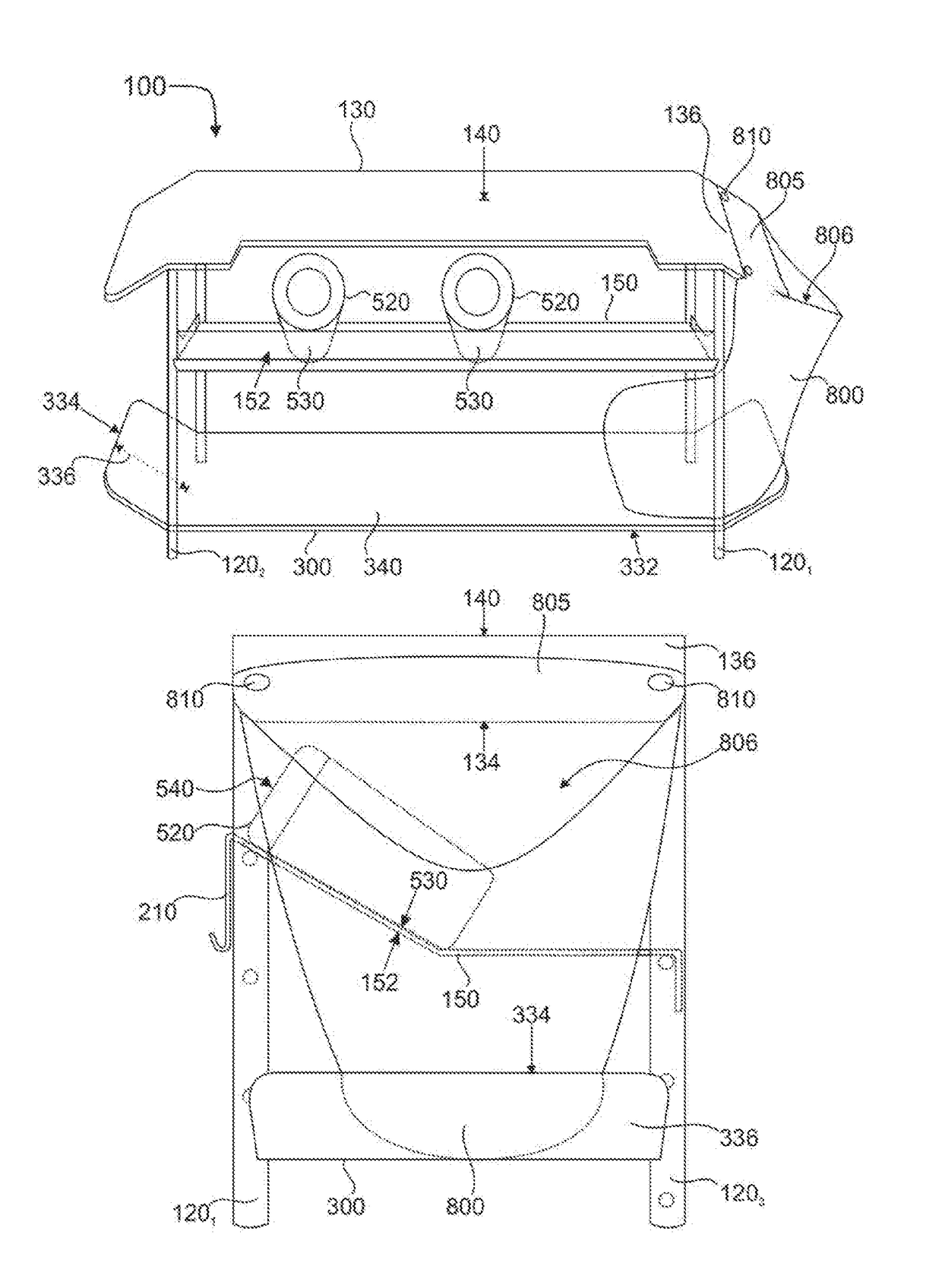
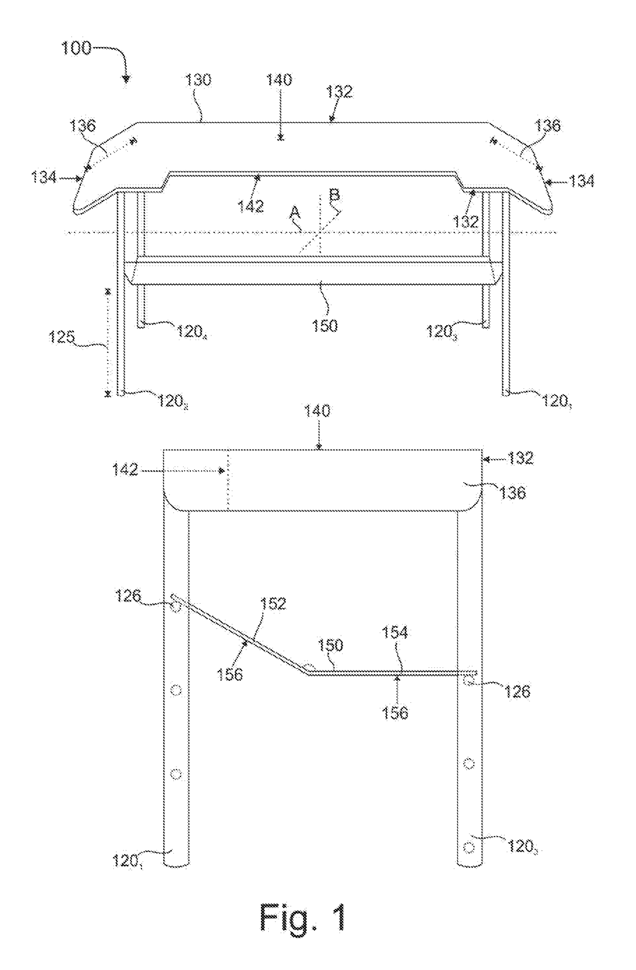
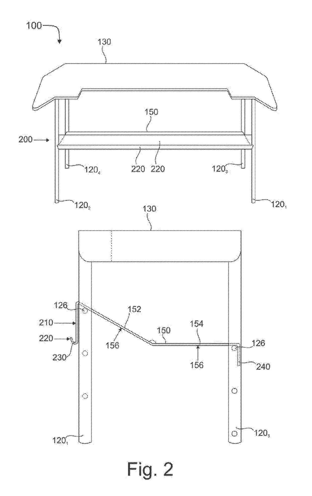
[0054]Referring now to the Figures, there is shown a medical support structure 100 according to the invention is shown in FIG. 1, which comprises a framework 110 having a main axis A and a transverse axis B (both shown in dotted line) and a plurality of substantially rectilinear, elongate leg members 1201-4. The structure 100 further comprises a substantially planar member 130 having a top surface 140, and locatable atop the framework 110. The structure 100 further comprises a supporting member 150 located intermediate the upper member 130 and a lower portion 125 of each of the plurality of leg members 1201-4.

[0055]In this embodiment, the upper member 130 is substantially rectangular, having parallel sides 132 that are longer in a direction parallel to the main axis A of the structure 100, and parallel ends 134 which are shorter than, and orthogonal to, the parallel sides 132. Adjacent each end 134, a portion 136 of the upper member 130 is angled downwardly relative to the main hori...

second embodiment

[0085]In a second embodiment shown in FIG. 8B, the releasable securing means again comprises two magnets 801, which in this embodiment here embedded at respective positions 802 within the material constituting the or each flange portion 136 of the planar member 130 adjacent its end 134, and have an upper surface coincident with or, if fully embedded within the member material, then closely adjacent, the top surface 140. In this embodiment, the releasable securing means further comprises a securing flat iron or bar 803 made from a ferrous or other magnetic material, which extends over at least the two embedded magnets 801 and a linear distance therebetween (shown at 804), and is releasable therefrom by overcoming the magnetic force which attracts the bar 803 to the magnets 801 and reciprocally.

[0086]When the bar 803 is released, a portion of the wall of a refuse container can again be abutted atop and cover a portion of the top surface 140 corresponding to at least a portion of the f...


PUM


Abstract

A medical support structure is disclosed, which comprising a framework having a main axis and comprising at least one supporting member and a plurality of leg members, and a top surface locatable atop the framework and adapted to support one or more refuse containers each having an aperture and a bottom portion. The supporting member is locatable intermediate the top surface and a lower portion of the plurality of leg members, and is adapted to support at least one medical waste container having an aperture and a bottom portion. At least a first longitudinal portion of the supporting member forms an obtuse angle relative to a second longitudinal portion of the supporting member so as to angle the or each medical waste containers in a position in which its aperture is higher than its bottom portion but not orthogonal to the top surface.

Description

CROSS-REFERENCE TO RELATED APPLICATIONS[0001]This application claims priority from Great Britain patent application number 1518596.0, filed Oct. 20, 2015, the disclosure of which is hereby incorporated by reference herein.BACKGROUND OF THE INVENTION[0002]Field of the Invention[0003]The present invention relates to improvements in medical support structures for use in medical environments. More particularly, the present invention relates to a multifunctional medical support structure for facilitating the streaming of refuse during medical procedures.[0004]Background Art[0005]Many medical support structures are known and used within healthcare environments. A wide variety of such structures have been developed for function-specific purposes, and include medical carts or trolleys developed to assist surgical or treatment procedures as disclosed in e.g. U.S. Pat. No. 5,765,842; carts or trolleys adapted to store and transport refuse as disclosed in e.g. U.S. Pat. No. 3,853,329; carts or...

Claims


Application Information

Patent Timeline
IPC IPC(8): A61B50/30B65F1/14A61M5/52B62B3/00
CPCA61B50/3001A61M5/52B65F1/141B62B3/002B62B3/005A61B50/13A61B50/15A61B50/36A47B37/00B65F1/0053
Inventor ROSS, JONATHAN JAMESHULLEY, TIMOTHY JOHN
Owner ROSS JONATHAN JAMES
Learn More