Parachute

a technology of parachute and ejection device, which is applied in the field of parachute, can solve the problems of user deceleration, user neck injury, and need for rapid deceleration, and achieve the effects of increasing the chance of excessive hyperextension or hyperflexion, increasing the mass of the user's head, and increasing the for

Inactive Publication Date: 2017-04-20
MARTIN BAKER AIRCRAFT
View PDF0 Cites 11 Cited by
  • Summary
  • Abstract
  • Description
  • Claims
  • Application Information

AI Technical Summary

Benefits of technology

[0004]During ejection from an aircraft, a parachute is deployed shortly after the pilot has cleared the vicinity of the aircraft, at or around the same time as the pilot separates from the ejection seat. It is often necessary to deploy the parachute as quickly as possible. At this point, the pilot could potentially be in a non-vertical orientation, not in full contact with the seat (out of position), travelling at a relatively high horizontal velocity, and / or not facing the direction of travel. The high deceleration forces, coupled with the awkward position of the pilot, increases the chances of excessive hyperextension or hyperflexion. The problems are compounded when the pilot is wearing a helmet, which may be provided with additional equipment (vision systems, sensors, breathing equipment etc). This increases the mass of the user's head and thus increases the forces imposed on a pilot's neck during parachute deployment, further increasing the risk of injury.

Problems solved by technology

As a parachute is initially deployed, the air resistance increases, causing deceleration of the user.
However, there is often a need for rapid deceleration, particularly in emergency situations or where the user's initial velocity is high.
High deceleration can potentially cause injury to the user's neck, where the neck muscles are unable to withstand the force put on them by the inertial forces caused by the user's relatively heavy head.
Excessive hyperextension or hyperflexion can cause significant injury.
The high deceleration forces, coupled with the awkward position of the pilot, increases the chances of excessive hyperextension or hyperflexion.
The problems are compounded when the pilot is wearing a helmet, which may be provided with additional equipment (vision systems, sensors, breathing equipment etc).
This increases the mass of the user's head and thus increases the forces imposed on a pilot's neck during parachute deployment, further increasing the risk of injury.

Method used


Image

  • Parachute
  • Parachute
  • Parachute

Examples


Embodiment Construction

[0029]A description of example embodiments of the invention follows.

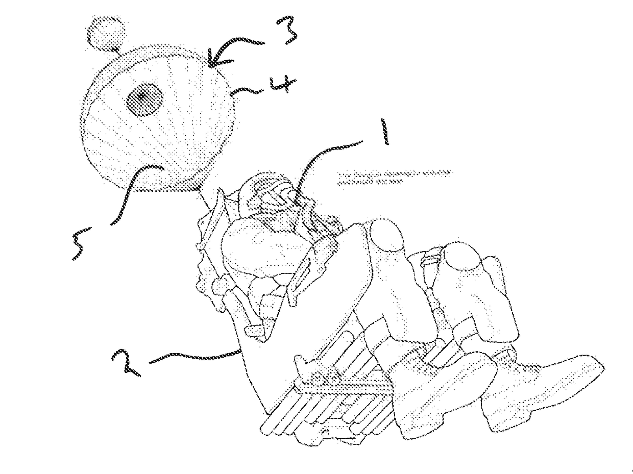
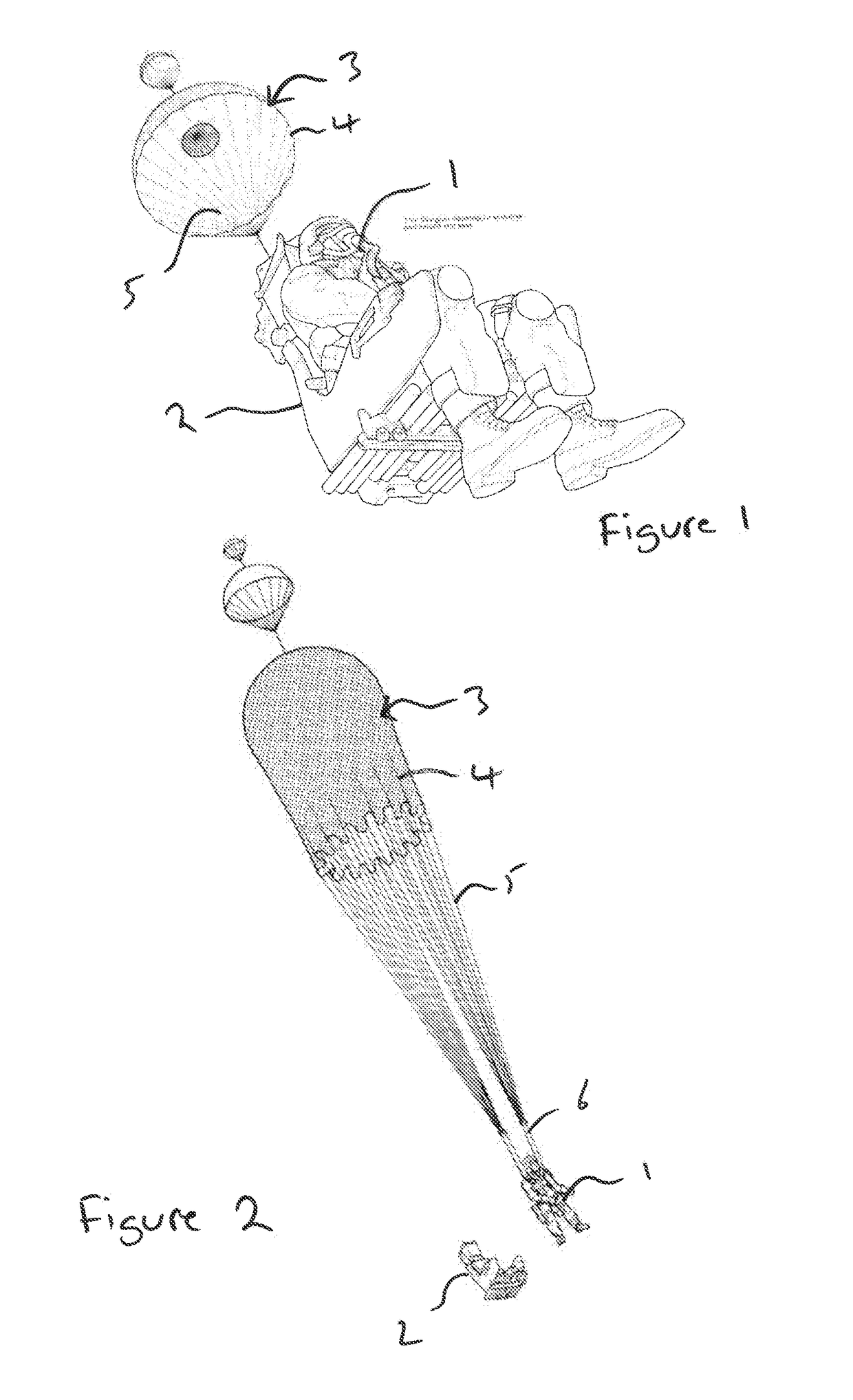
[0030]FIG. 1 illustrates a user (pilot) 1 seated in an ejection seat 2 having ejected from an aircraft (not shown). The user 1 is secured to the ejection seat 2 by a connection such a harness. Preferably, the user 1 is wearing a body harness which is separately secured to the seat 2. A parachute 3 is connected to the harness of the user 1. The parachute 3 comprises a canopy 4 secured to a plurality of suspension lines 5 which are secured to a plurality of risers 6. The risers 6 are secured to the user's 1 harness.

[0031]As the parachute 3 is deployed, the user 1 separates from the seat 2, in a known manner, as shown in FIG. 2.

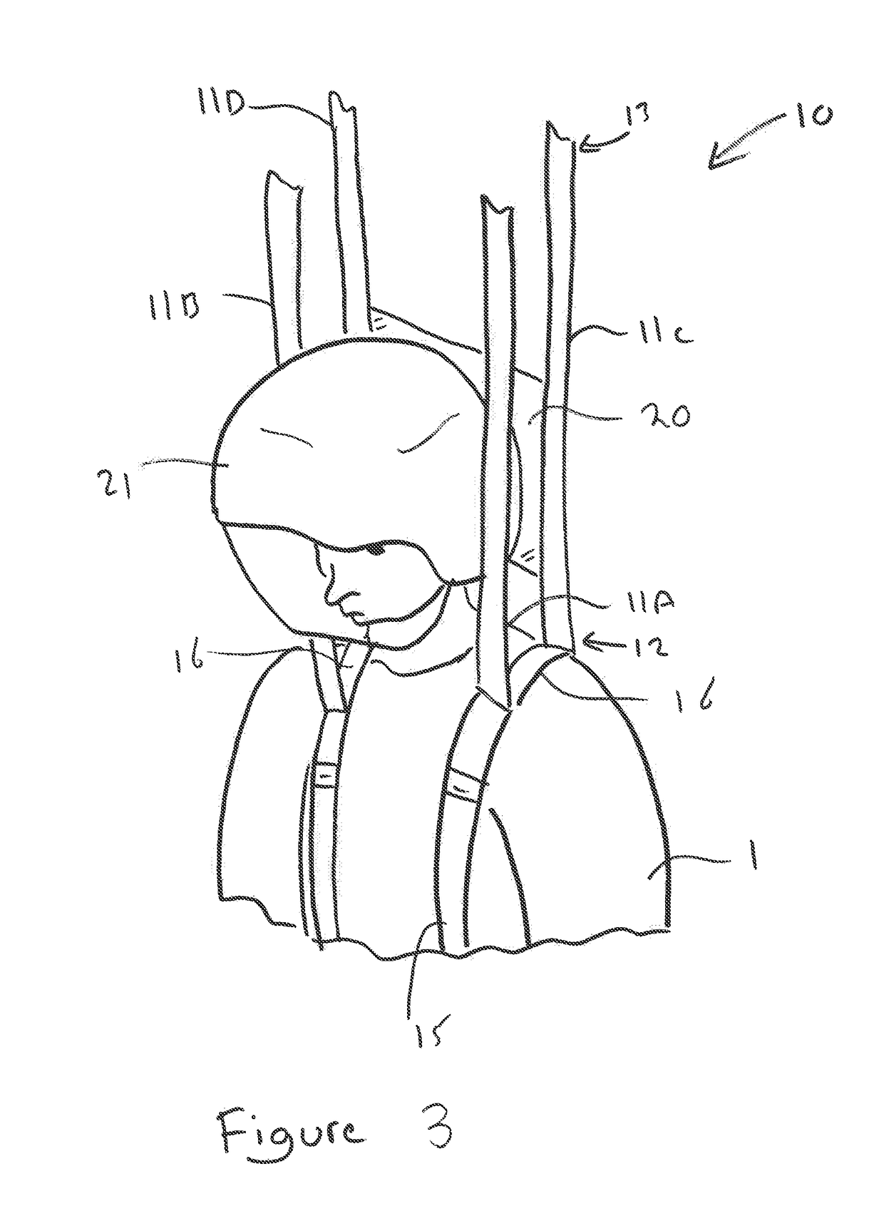
[0032]As discussed above, as the parachute deploys, the forces imposed on the user's neck can cause injury.

[0033]FIG. 3 illustrates part of a parachute 10 embodying the present invention. The canopy and suspensions lines are not shown but can take the conventional form of the canopy 4 and suspen...


PUM


Abstract

A parachute comprising:
a canopy;
a plurality of risers connected at each of their respective first ends to the canopy and connectable at each of their respective second ends to a harness; and
a panel extending between at least two of the plurality of risers,
configured such that when the parachute is deployed, a user's head is positioned generally between the plurality of risers and the panel is arranged behind the user's head to provide support thereto.

Description

RELATED APPLICATION[0001]This application claims priority under 35 U.S.C. §119 or 365 to United Kingdom Application No. GB 1518333.8, filed Oct. 16, 2015. The entire teachings of the above application are incorporated herein by reference.BACKGROUND[0002]The present invention relates to a parachute and particularly to an ejection seat comprising a parachute. The present invention further provides a chin support pad.SUMMARY OF THE INVENTION[0003]As a parachute is initially deployed, the air resistance increases, causing deceleration of the user. The deceleration forces can be controlled to some extent by the use of a conventional slider. However, there is often a need for rapid deceleration, particularly in emergency situations or where the user's initial velocity is high. High deceleration can potentially cause injury to the user's neck, where the neck muscles are unable to withstand the force put on them by the inertial forces caused by the user's relatively heavy head. The force ca...

Claims


Application Information

Patent Timeline
Patent Type & Authority Applications(United States)
IPC IPC(8): B64D25/06B64D17/30B64D25/10
CPCB64D25/06B64D17/30B64D25/10B64D17/00A42B3/08B64D17/24B64D17/62
Inventor ADAMS, PAULGODDARD, JULIEELSON, MARK
Owner MARTIN BAKER AIRCRAFT
Why Eureka
Try Eureka