
Dual rotating electric toothbrush

a technology of electric toothbrushes and rotating teeth, which is applied in the direction of brushes, cleaning equipment, carpet cleaners, etc., can solve the problems of not having utilized or disclosed a protective shield, one or more secondary problems or cannot reach the intended goal, and can not reach the intended goal very efficiently, so as to stop or minimize the splashing of saliva, avoid the effect of wasting resources

Active Publication Date: 2013-11-19
DJANG SAM
View PDF19 Cites 6 Cited by
  • Summary
  • Abstract
  • Description
  • Claims
  • Application Information

AI Technical Summary

Benefits of technology

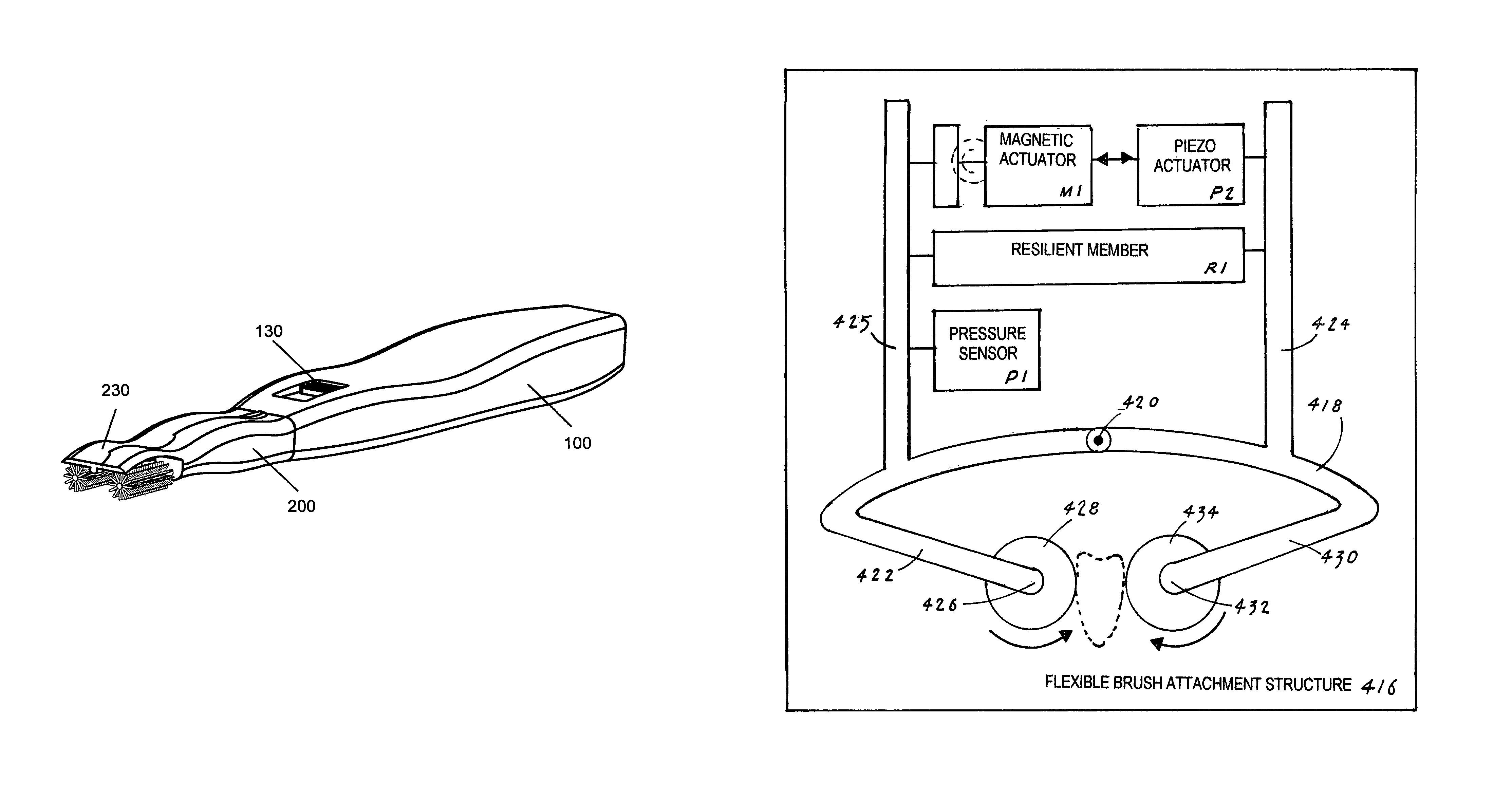
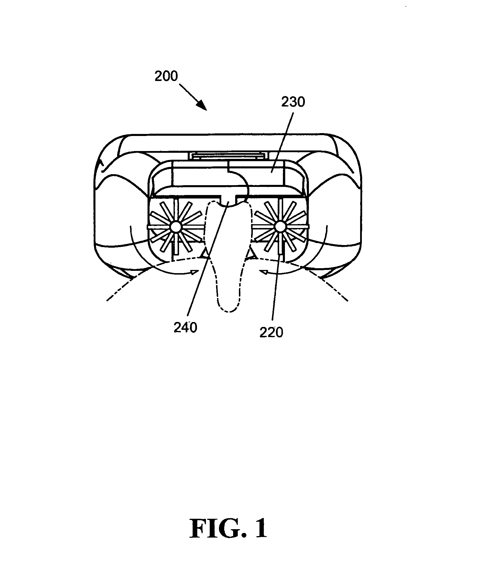
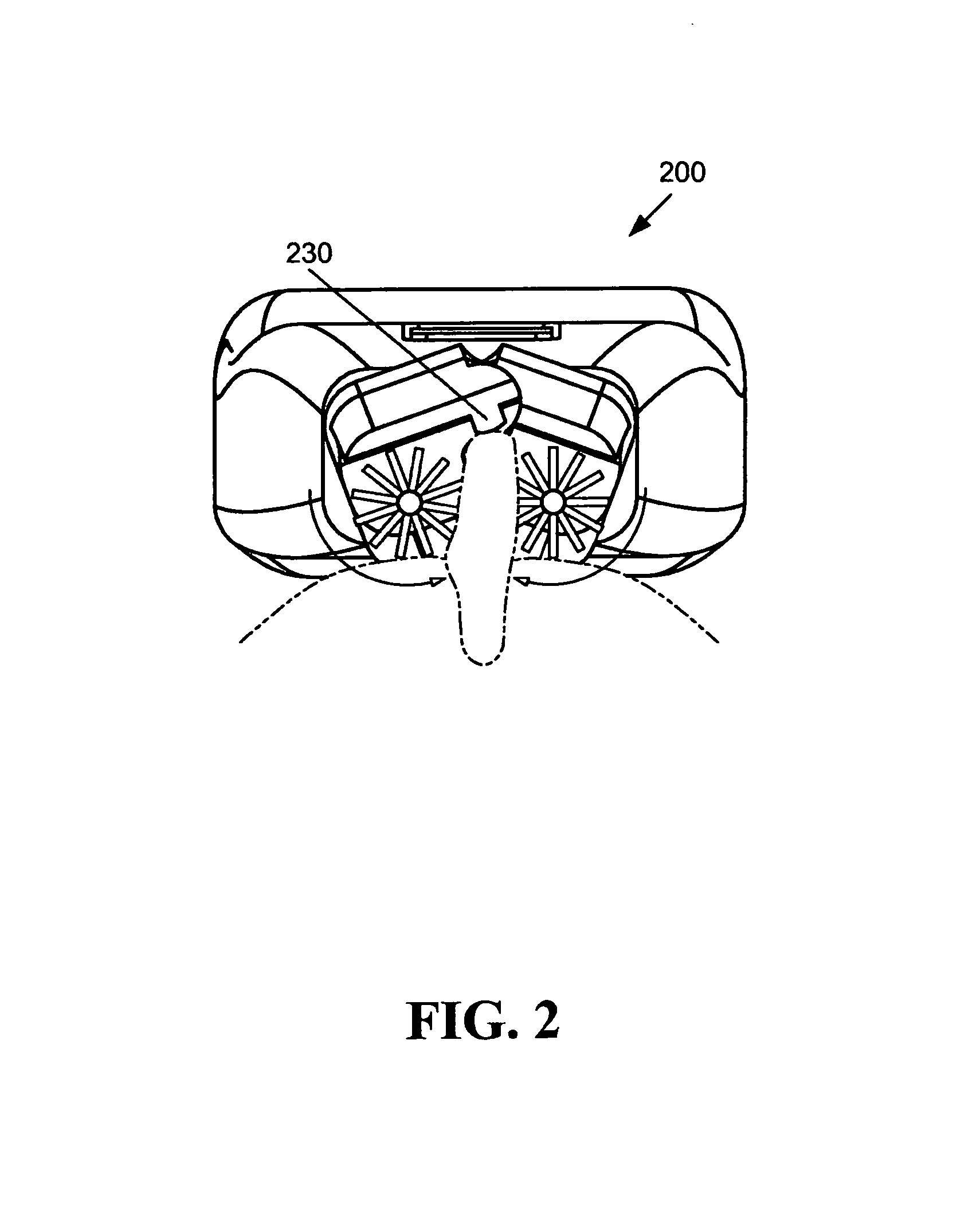
The technology described in this patent is a dual rotating electric toothbrush with two lines of bristles that rotate inward from each side, giving a brushing effect on both buccal and lingual surfaces of the tooth. This ideal brushing direction should be on the long axis of the tooth, from the gum tissue to the tooth direction. The toothbrush can slide in a bucoc-lingual direction and the user can push the switch to move the brush in front of their teeth to clean the narrow front teeth. The covering works as a protective shield to stop or minimize the splashing out of saliva and / or toothpaste from a user's mouth. Additionally, the guiding stop at the middle part of the head tip of the brush helps guide the user to the correct position for a tooth.

Problems solved by technology

Present manual and electrical toothbrushes can not reach these areas very efficiently.
However, since the designers of these toothbrushes apparently ignored major or minor structural parts or system in their designs, their products can lead to one or more secondary problems or can never reach the intended goal.
While these patents and other previous methods have attempted to solve the problems that they addressed, none have utilized or disclosed a protective shield directed to addressing soft tissue irritation, oral cavity malignancies and splashing, and / or a guiding stop directed to proper tooth positioning of the device, as does embodiments of the technology described herein.

Method used


Image

  • Dual rotating electric toothbrush
  • Dual rotating electric toothbrush
  • Dual rotating electric toothbrush

Examples


Embodiment Construction

[0050]The technology described herein will now be described in detail with reference to at least one preferred embodiment thereof as illustrated in the accompanying drawings. In the following description, numerous specific details are set forth in order to provide a thorough understanding of the technology described herein. It will be apparent, however, to one skilled in the art, that the technology described herein may be practiced without some or all of these specific details. In other instances, well known operations have not been described in detail so not to unnecessarily obscure the technology described herein.

[0051]Referring to FIGS. 1-19, like reference numerals designate corresponding parts throughout the figures, reference is made first to FIG. 1 which illustrates a head assembly 200.

[0052]The dual rotating electric toothbrush is comprised of a body assembly 100 and a head assembly 200. In an exemplary embodiment the length of the body assembly 100 ranges from 6-7 inches, ...


PUM


Abstract

A powered, mechanical teeth cleaning device having a pair of rotating brushes. The brushes rotate inward from each side, providing a cleaning effect on both buccal and lingual surfaces of a tooth from the gum tissue to the tooth. The toothbrush automatically adjusts the pressure applied to the pair of brushes in response to the width of a particular interfacing tooth. The toothbrush also has protective shield for minimizing mouth tissue irritation, and a guiding stop for proper tooth positioning.

Description

[0001]This application is a Continuation-In-Part (CIP) of application Ser. No. 11 / 850,388 filed Sep. 5, 2007 now abandoned.TECHNICAL FIELD[0002]The invention generally pertains to electrically driven teeth cleaning devices, and more particularly to a dual rotating electric toothbrush that automatically adjusts the pressure applied to the teeth.BACKGROUND ART[0003]For a long time specialists have agreed that in order to be effective, teeth must be brushed from the gum towards the end of the tooth, i.e, downwards for the top jaw and upwards for the bottom jaw.[0004]It has been a long standing need to make a perfect tooth cleaning device. Most dental decay and gum problems start from the area called embrasure, which is the space located between two adjacent teeth and the gum line. Present manual and electrical toothbrushes can not reach these areas very efficiently. In addition, brushing direction is important to protect the gum line from receding. To achieve this goal, the brushing di...

Claims


Application Information

Patent Timeline
Patent Type & Authority Patents(United States)
IPC IPC(8): A61C17/26
CPCA46B5/0012A61C17/26A46B15/0012A46B9/045A46B2200/1066
Inventor DJANG, SAM
Owner DJANG SAM
Learn More