Speckle reduction instrument

a technology of speckle reduction and laser, which is applied in the field of laser speckle reduction, can solve the problems of insufficient imaging brightness of conventional methods of speckle reduction, and the microscopes that use ir lasers for illumination produce “noisy” images, so as to reduce the coherence of lasers, improve image quality, and reduce speckle

Active Publication Date: 2018-10-11
THE UNITED STATES OF AMERICA AS REPRESENTED BY THE SECRETARY OF THE NAVY
View PDF6 Cites 1 Cited by
  • Summary
  • Abstract
  • Description
  • Claims
  • Application Information

AI Technical Summary

Benefits of technology

[0009]The present invention provides a speckle reduction instrument and method for reducing speckle for a variety of applications, including standoff detection. It provides a device and method for reducing coherence of laser (especially infrared) light without significant loss of laser power. With this invention, laser light that is highly coherent is converted into less-coherent but still bright light suitable for illumination in microscopes and other devices. This achieves significant improvement in image quality in imaging applications, including microscopy.
[0011]The speckle reduction device of the present invention has a parabolic reflector and flat mirror that form a cavity. Diffused laser light bounces back and forth between the parabolic reflector and the flat mirror. All diffused light is collected and bounced around the cavity. The laser will effectively hit the diffuser surface multiple times, which improves de-speckling performance. Ideally, the cavity should be slightly de-tuned so consecutive reflections hit different parts of the diffuser.
[0012]There are several advantages with the present invention. It provides higher optical throughput (efficiency) than current methods. It has an adjustable control of the amount of decoherence (trade-off between laser power and level of decoherence). It results in more useful (collimated) incoherent light. Unlike in an integrating sphere, rays stay close to on-axis. The cavity design allows multiple passes leading to increased speckle reduction. A slightly defocusing laser spot increases the diffuser area seen by the laser spot providing more chances to de-cohere.

Problems solved by technology

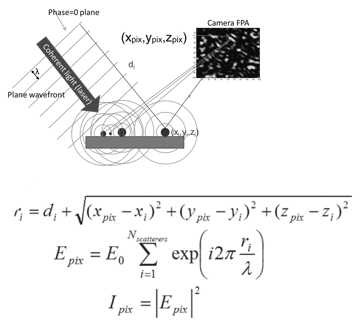
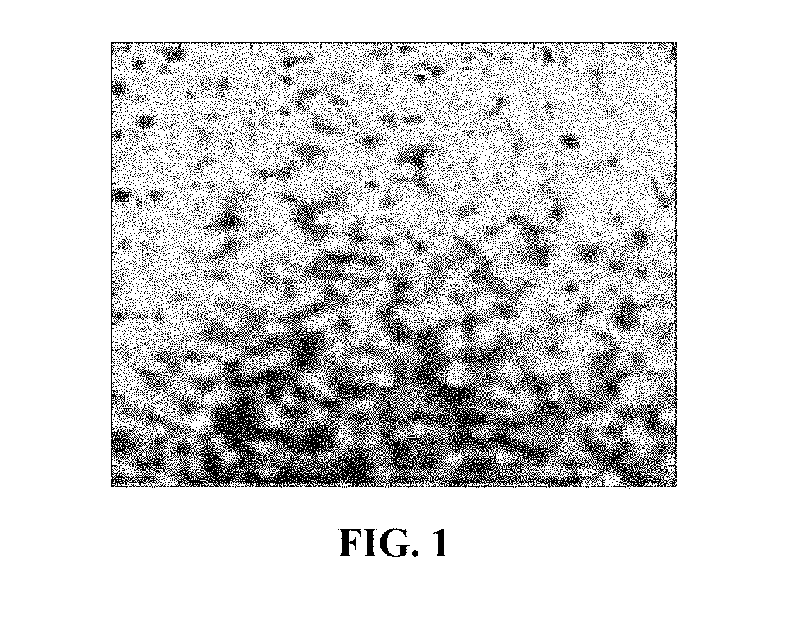
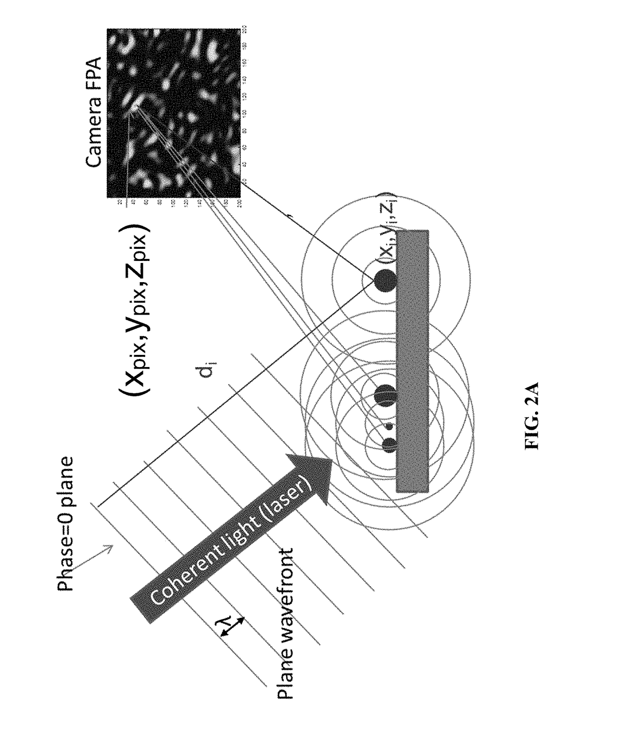
Infrared (IR) microscopes that use IR lasers for illumination produce “noisy” images due to speckle effects.
Conventional methods for speckle reduction don't provide enough brightness for imaging.

Method used


Image

  • Speckle reduction instrument
  • Speckle reduction instrument
  • Speckle reduction instrument

Examples


Embodiment Construction

[0017]The prevent invention relates to speckle reduction and a high optical throughput speckle reduction device. To increase the throughput, a cavity-based unit (see FIG. 3) was designed that captures most of the hemispheric diffused reflectance emitted by the diffuser. One mirror in the cavity has a parabolic profile and collimates all collected rays towards a flat mirror. This flat mirror has a central opening where a spinning disk diffuser is inserted. The parabolic mirror also has a central hole through which the incoming laser beam is focused onto the diffuser. Another off-center hole in the flat mirror allows a certain percentage of light to exit the unit with each pass in the cavity. This light is either coupled into an optical fiber or used free-space. Slightly defocusing the incoming laser beam or moving the spinning disk away from the plane of the flat mirror allows for control of the amount of speckle reduction and optical throughput the unit can provide.

[0018]The diffuse...


PUM


Abstract

A speckle reduction instrument having a parabolic reflector and flat mirror to form a cavity-based unit. Laser light is collected and bounced around the cavity hitting a diffuser surface multiple times. The laser light that is highly coherent is converted into less-coherent but still bright light suitable for illumination in microscopes and other devices. Also disclosed is the related method for reducing speckle.

Description

PRIORITY CLAIM[0001]The present application is a non-provisional application claiming the benefit of U.S. Provisional Application No. 62 / 482,646 filed on Apr. 6, 2017 by Robert Furstenberg et al., entitled “SPECKLE REDUCTION INSTRUMENT,” the entire contents of which is incorporated herein by reference.CROSS REFERENCE[0002]Cross reference is made to application Ser. No. ______, filed contemporaneously herewith, entitled LASER SPECKLE REDUCTION AND PHOTO-THERMAL SPECKLE SPECTROSCOPY, by Robert Furstenberg et al., (Attorney Docket No. 106031-US2) the disclosure and contents of which are incorporated herein by reference in its entirety.BACKGROUND OF THE INVENTIONField of the Invention[0003]The present invention relates to laser speckle reduction, and more particularly to a high-throughput speckle reduction device.Description of the Prior Art[0004]Due to their high brightness, infrared (IR) lasers (such as tunable quantum cascade lasers (QCLs)) are very attractive illumination sources in...

Claims


Application Information

Patent Timeline
Patent Type & Authority Applications(United States)
IPC IPC(8): G02B27/48G02B27/09G02B5/02
CPCG02B27/48G02B27/0983G02B27/0994G02B5/0284
Inventor FURSTENBERG, ROBERTKENDZIORA, CHRISMCGILL, R. ANDREW
Owner THE UNITED STATES OF AMERICA AS REPRESENTED BY THE SECRETARY OF THE NAVY
Why Eureka
Try Eureka