Automated liquid treatment management unit and control methods

a technology of liquid treatment and management unit, applied in the field of liquid cleaning in industrial processes, can solve the problems of large quantity of fracking, large amount of fracking, and large power supply installation and/or site preparation, and achieve the effects of reducing cost, enhancing throughput, and effective and safe water treatmen

Inactive Publication Date: 2017-04-20
ROCKWATER RESOURCE
View PDF3 Cites 6 Cited by
  • Summary
  • Abstract
  • Description
  • Claims
  • Application Information

AI Technical Summary

Benefits of technology

[0006]This invention provides a liquid treatment station and plural mobile treatment units and methods for control and operation thereof. This invention is particularly well adapted for improved industrial process water treatment, for example flowback water treatment at oil and gas hydraulic fracturing sites. The station has separate mobile treatment and mobile treatment management units, the mobile liquid treatment unit being greatly improved over similar heretofore utilized treatment technologies. The liquid treatment management unit controls operation of the liquid treatment unit and provides control of chemical dosing. The station and units of this invention require minimal utility support / supply and site preparation, provide effective and safe treatment of water, and have enhanced throughput at reduced cost at industrial treatment sites such as oil and gas drilling and production sites. The units thereby reduce water hauling and related costs to well sites and waste water hauling away from well sites, while conserving water resources.
[0011]The treatment unit includes at least seven water containment and treating compartments (preferably eight, including a buffer compartment). The structure for liquid inflow include a plurality of intervening diving structures one of adjacent to or located between at least some of the compartments for receiving and directing liquid to an adjacent compartment at the lower portion thereof. Each of the compartments has flow accommodating components thereat. At least some of the compartments include liquid flow leveling features for independent adjustment of the flow accommodating components in both longitudinal and transverse directions. The features thereby selectively compensate for unlevel location of the mobile platform at a treatment site and thus unit sloping.
[0021]It is yet another object of this invention to provide a mobile liquid treatment station and methods that provide effective and safe treatment of water and have enhanced throughput at reduced cost at industrial treatment sites such oil and gas drilling and production sites.
[0022]It is still another object of this invention to provide a mobile liquid treatment station having mobile units and methods that reduce water hauling to and from treatment sites, use of precious water supply and water treatment resources, and related costs.
[0027]It is still another object of this invention to provide a mobile liquid treatment unit locatable at a selected site having a mobile platform with a foul liquid intake end and a purified liquid output end, and a plurality of liquid containment and treating compartments defined at the mobile platform and serially arranged between the ends to provide cascading flow between at least some of the compartments and each having flow accommodating components thereat, at least some of the compartments including liquid flow leveling features for independent adjustment of the flow accommodating components located therein in both longitudinal and transverse directions to selectively compensate for unlevel location of the mobile platform at the site and thus unit sloping.

Problems solved by technology

These units have often required extensive power supply installations and / or site preparations (leveling, leak sealing and the like).
Moreover, such devices have not proven entirely effective (in terms of treatment efficacy, throughput and / or cost) for many industrial uses, particularly in the field of oil and gas drilling and production.
However, fracking utilizes large quantities of water at the well site, often taken from a regional water supply having numerous alternative uses including industrial, agricultural and municipal uses.
Trucking flowback fluids offsite for disposal or treatment is expensive.

Method used


Image

  • Automated liquid treatment management unit and control methods
  • Automated liquid treatment management unit and control methods
  • Automated liquid treatment management unit and control methods

Examples


Embodiment Construction

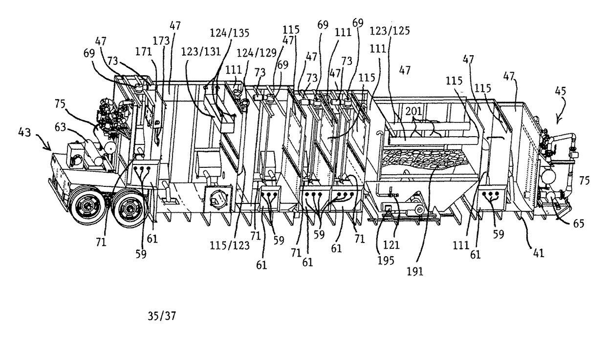
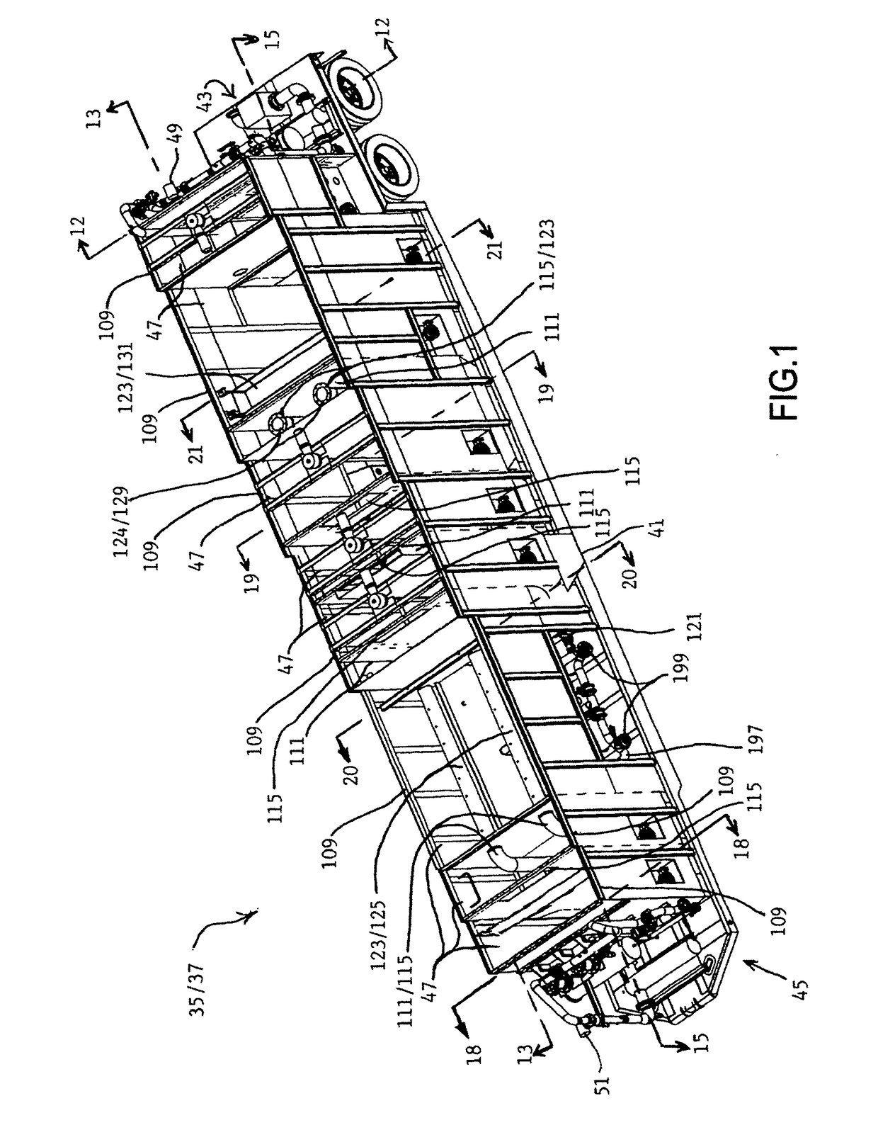
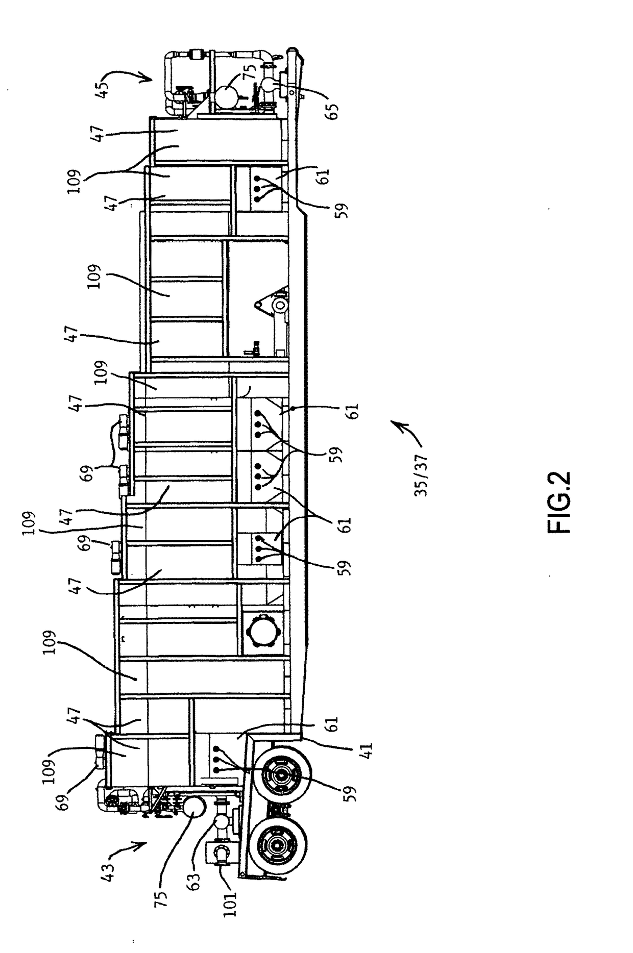
[0066]A mobile liquid treatment station 35 of this invention is illustrated in the FIGURES. The station can be used at selected sites in any number of liquid (primarily water) treatment applications, and, as illustrated herein, is well adapted for treating industrial process liquids, such as flowback water at oil and gas fracking sites. The station includes primary mobile liquid treatment unit 37 (see FIGS. 1 through 21) and independently mobile treatment management unit 39 (see FIGS. 22 through 25). Each unit 37 / 39 is mounted on a mobile (wheeled) platform 41, typical two axle long haul trailers, for example.

[0067]Mobile primary liquid treatment unit 37 has an intake end 43 for receipt of liquid to be treated (hereinafter “foul liquid” or “foul water”, for example fracking process flowback water) and a purified liquid output end 45 with a plurality of liquid containment and treatment compartments 47 defined and serially arranged therebetween. The compartments are dimensioned and lo...


PUM

PropertyMeasurementUnit
flow rateaaaaaaaaaa
pressure dropaaaaaaaaaa
volumeaaaaaaaaaa

Abstract

A mobile liquid treatment station and operation methods are disclosed, the station having a mobile treatment unit and separate mobile treatment management unit. A plurality of serial containment compartments at the treatment unit for performance of chemical dosing and solids separation are provided and are monitored with sensors. The management unit includes a plurality of chemical dosing platforms, and a power and processing assembly. A bus links the units for data and control signal transfer and chemical feed lines are connected between the units for transfer of dosing chemicals.

Description

RELATED APPLICATION[0001]This application is a Continuation of pending U.S. patent application Ser. No. 13 / 987,088 by the Inventors herein filed Jul. 1, 2013 and entitled LIQUID TREATMENT STATION INCLUDING PLURAL MOBILE UNITS AND METHODS FOR OPERATION THEREOF.FIELD OF THE INVENTION[0002]This invention is related to cleaning of liquids, especially water, and more particularly relates to industrial process liquid cleaning at remote locations such as oil or gas well drilling sites and the like.BACKGROUND OF THE INVENTION[0003]Mobile water treatment units have been heretofore suggested and / or utilized for various purposes including facilities modeling (see U.S. Patent Publication No. 2009 / 0032346), emergency or remote water supply (see U.S. Pat. Nos. 6,464,884, 5,632,892, 6,120,688, and 6,228,255), mining and industrial uses (see U.S. Pat. Nos. 4,383,920, 5,558,775, 5,547,584 and 6,607,668, and U.S. Patent Publication No. 2012 / 0312755), and addressing polluted water sources and waterway...

Claims


Application Information

Patent Timeline
Patent Type & Authority Applications(United States)
IPC IPC(8): C02F9/00E21B43/34
CPCC02F9/00E21B43/34C02F2101/32C02F2101/20E21B43/26C02F2201/008C02F1/56C02F1/685C02F1/5209C02F2103/10C02F1/001C02F1/008C02F2209/42E21B43/2607E21B43/35B01D17/0208B01D17/047C02F1/5236C02F1/66C02F2209/11
Inventor WIEMERS, REGINALD A.KHALILI, BARDIA B.ROEDER, WERNER
Owner ROCKWATER RESOURCE
Why Eureka
Try Eureka