Airfoil for axial flow machine

a technology of airfoil and axial flow, which is applied in the direction of machines/engines, stators, liquid fuel engines, etc., can solve the problems of increased weight of the outlet guide vane, difficult weight reduction of the aircraft engine, and increased weight of the fan, so as to improve the vibration resistance of the end wall

Active Publication Date: 2017-04-20
IHI CORP
View PDF8 Cites 2 Cited by
  • Summary
  • Abstract
  • Description
  • Claims
  • Application Information

AI Technical Summary

Benefits of technology

[0018]According to the present disclosure, the axial flow machine blade that has attained promotion of weight reduction of the gas

Problems solved by technology

However, when such a rib is formed, the weight of the outlet guide vane is increased and weight reduction of the fan, in other words, weight reduction of the aircraft engine becomes difficult.
The same problem is also generated in a case where a shroud has been provided on an end portion of the outlet guide vane located rada

Method used


Image

  • Airfoil for axial flow machine
  • Airfoil for axial flow machine
  • Airfoil for axial flow machine

Examples


Embodiment Construction

[0028]The present disclosure is based on the following findings obtained by the inventors of the present application.

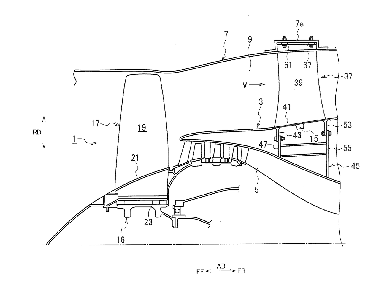
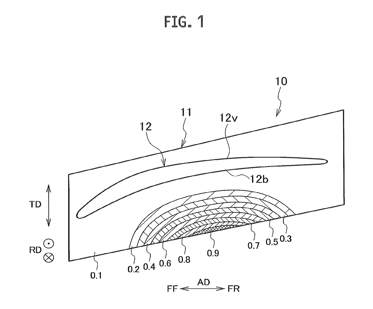
[0029]FIG. 1 is a diagram showing one example of an analysis result of a primary vibration mode generated on an end wall 11 of an airfoil 10 as an analysis object. In FIG. 1, [FF] indicates the upstream side (a forward direction) of a channel that an airfoil body 12 is installed, [FR] indicates the downstream side (a rear direction) of the channel concerned, [AD] indicates an axial direction, [RD] indicates a radial direction, [TD] indicates an airfoil thickness direction, respectively. The end wall 11 is a plate-shaped member that extends from the upstream side to the downstream side, constitutes a wall (a wall surface) of the channel as a platform that is provided on an end portion of the airfoil 10 located radially inside or as a shroud that is provided on an end portion of the airfoil 10 located radially outside. The end wall 11 supports the airfoil body 12 of the...


PUM


Abstract

An airfoil for an axial flow machine includes: an airfoil body extending in a radial direction; a platform (an end wall) provided at an end portion of the airfoil body in the radial direction, the end wall being formed into a plate shape as a wall of a channel in which the airfoil body is installed and which supports the airfoil body; and at least one convex portion formed so as to protrude from a back surface of the platform in a direction away from the airfoil body. The convex portion is formed integrally with a portion for generating a node of a primary vibration mode when an edge portion of the platform vibrates as a free end of the primary vibration mode.

Description

CROSS REFERENCE TO RELATED APPLICATIONS[0001]This application is a continuation application of International Application No. PCT / JP2015 / 071709, filed on Jul. 30, 2015, which claims priority to Japanese Patent Application No. 2014-232452, filed on Nov. 17, 2014, the entire contents of which are incorporated by reference herein.BACKGROUND[0002]1. Technical Field[0003]The present disclosure relates to an airfoil for an axial flow machine constituting a part of a gas turbine and the like.[0004]2. Description of the Related Art[0005]As is well known, the axial flow machine constituting a part of the gas turbine engine such as an aircraft engine includes rotor blades and stator vanes that perform compression of a fluid flowing in an axial direction. Some of these airfoils are enlarged along with recent development of the gas turbine engine. For example, as one of them, there is an outlet guide vane (OGV) that is a constitutional element of a fan sucking the outside air (refer to Japanese ...

Claims


Application Information

Patent Timeline
IPC IPC(8): F01D25/06F04D29/32F04D29/54F04D29/66F01D9/04F01D5/16
CPCF01D25/06F01D9/041F01D5/16F05D2250/711F04D29/66F04D29/324F05D2220/323F04D29/542F01D5/10F01D5/26F01D9/02F01D25/00F01D5/141F04D29/644F04D29/54
Inventor OGAWARA, KAZUTOSHIMADA, TAKAHIRO
Owner IHI CORP
Why Eureka
Try Eureka