Distributing power between data centers

a data center and power distribution technology, applied in the field of data centers, can solve the problems of large (excess) number of solar panels and storage batteries, the inability of data centers to operate exclusively on electric power based on renewable energy, and the inability to guarantee the stability of electric power supply to the data center, so as to achieve stable execution of jobs and stable execution of jobs

Active Publication Date: 2017-04-20
IBM CORP
View PDF6 Cites 0 Cited by
  • Summary
  • Abstract
  • Description
  • Claims
  • Application Information

AI Technical Summary

Benefits of technology

[0005]Therefore, it is an object of the present invention to enable the steady execution of jobs to be processed while predicting the amount of electric power being supplied to data centers operable using only electric power based on renewable energy. It is another object of the present invention to properly share and stably execute jobs to be processed between data centers while predicting the amount of electric power being supplied to each data center.

Problems solved by technology

When a data center is operated using electric power generated from renewable energy such as wind power or solar power, the supply of electric power to the data center is not always stable.
In other words, data centers currently cannot operate exclusively on electric power based on renewable energy.
There are examples of data centers drawing all of their electric power from photovoltaic cells but, in order to provide a constant supply of photovoltaically generated electric power to a data center given the instability of available sunlight, a large (excess) number of solar panels and storage batteries is required, which makes installation costs higher than they would otherwise be.
When considering the installation of a data center in a location without transmission lines, there is concern over the inability to supply electric power to the data center from the grid in an emergency.

Method used


Image

  • Distributing power between data centers
  • Distributing power between data centers
  • Distributing power between data centers

Examples


Embodiment Construction

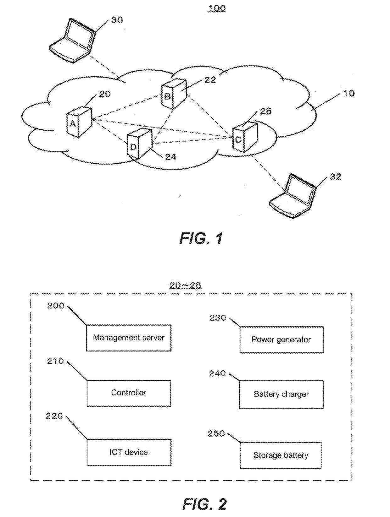
[0039]The following is an explanation of an embodiment of the present invention with reference to the drawings. FIG. 1 is a diagram showing a configuration example of a data center network system according to an embodiment of the present invention. The network system 100 includes a communication network 10, four data centers (A-D) 20-26 in the communication network 10, and computers (terminals) 30, 32 that can be connected to the communication network 10. Each data center computer can communicate with other data centers and computers (terminals). The communication paths in FIG. 1 are denoted by the dotted lines. These communication paths can be wired or wireless communication paths. The number of data centers and terminals shown in FIG. 1 is just an example, and the scale of the network system can be increased or decreased.

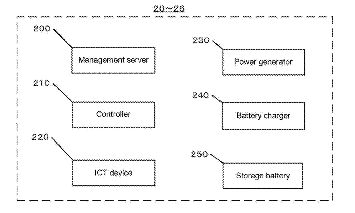
[0040]FIG. 2 is a diagram showing a configuration example of one of the data centers 20-26 in FIG. 1. Each data center includes a management server 200, a control...


PUM


Abstract

A data center operable using only electric power based on renewable energy. The data center includes at least one device driven by the electric power, a storage battery for storing the electric power, and a controller for switching the operating mode of the device over the course of time on the basis of predicted values for the amount of electric power generated using renewable energy, the amount of electric power stored in the storage battery, and the amount of electric power consumed by the device.

Description

BACKGROUND[0001]The present invention relates to a data center and, more specifically, to a method for distributing a load between data centers that are operable using only electric power based on renewable energy.[0002]When a data center is operated using electric power generated from renewable energy such as wind power or solar power, the supply of electric power to the data center is not always stable. Therefore, hardly any data centers rely exclusively on renewable energy at the present time. For example, some data centers use some power generated photovoltaically but draw the remaining demand from ordinary transmission lines. In other words, data centers currently cannot operate exclusively on electric power based on renewable energy.[0003]There are examples of data centers drawing all of their electric power from photovoltaic cells but, in order to provide a constant supply of photovoltaically generated electric power to a data center given the instability of available sunligh...

Claims


Application Information

Patent Timeline
Patent Type & Authority Applications(United States)
IPC IPC(8): H02J3/38H02J7/00
CPCH02J3/383H02J7/0052H02J3/386H02J9/061G06F1/3212G06F9/5094H02J7/35Y02B10/70Y02D10/00Y02E10/76H02J7/00H02J3/003Y02B70/10
Inventor NARITA, IZURU
Owner IBM CORP
Why Eureka
Try Eureka