Automatic swath generation device and methods

a technology of automatic swath generation and swath generation, which is applied in the direction of vehicle position/course/altitude control, process and machine control, instruments, etc., can solve the problems of not only requiring resources, time and fuel, but also constant updating

Active Publication Date: 2017-04-27
BLUE LEAF I P INC
View PDF3 Cites 8 Cited by
  • Summary
  • Abstract
  • Description
  • Claims
  • Application Information

AI Technical Summary

Benefits of technology

[0011]An advantage of the present invention is the user can drive the vehicle normally through a field before allowing the controller to automatically select a swath path to follow.
[0012]Another advantage is the vehicle can automatically produce headland and infill areas without the user being required to mark a base swath path while driving the vehicle.
[0013]Yet another advantage is the vehicle can be controlled to follow swath paths that are perpendicular to one another adjacent to corners of the field, which can better cover the corner than rounded patterns.

Problems solved by technology

Such physical characteristics and limitations may include width, location of the implement with respect to the vehicle, and limitations of movement, such as minimum turning radius.
This not only requires resources such as time and fuel, but can require constant updating if the field boundaries change.
Some automatic guidance control systems are capable of creating guidance lines based on points defining the field boundaries, but such systems produce swath patterns that leave gaps in the corners of the field.
Further, users have to manually drive the vehicle in the corners to get the implement pulled by the vehicle exactly lined up in the corner of the field, which is an inconvenience.
Even further, current systems require that the user selects which guidance line the automatic guidance control system follows, which might result in the user selecting a less than optimal guidance line for the vehicle's location in the field.

Method used


Image

  • Automatic swath generation device and methods
  • Automatic swath generation device and methods
  • Automatic swath generation device and methods

Examples


Embodiment Construction

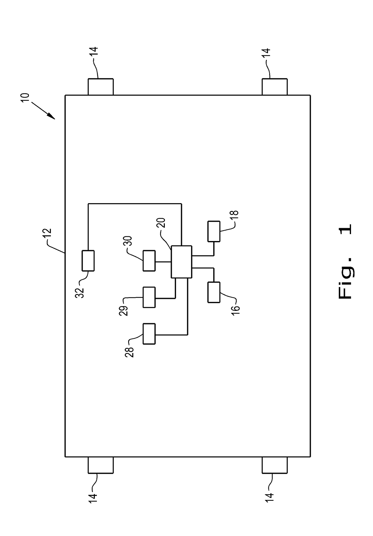
[0021]Referring now to the drawings, and more particularly to FIG. 1, there is shown a block diagram of an embodiment of an agricultural vehicle 10 according to the present invention which generally includes a chassis 12, traction members 14, such as wheels, carried by the chassis 12, an automatic guidance control system 16 carried by the chassis 12, a memory unit 18 carried by the chassis 12, and a controller 20 coupled to the automatic guidance control system 16 and the memory unit 18. The vehicle 10, shown as a tractor in FIG. 3, can also include an agricultural implement 22 that is pulled by the chassis 12 as the tractor 10 travels. The automatic guidance control system 16 can be any sort of suitable guidance system that can change a direction of the wheels 14 to control the travel direction of the vehicle 10 without the need for the user to directly control the wheels 14 with, for example, a steering wheel. Such guidance systems are known in the art and further description is o...


PUM


Abstract

A method for automatically generating swath paths and navigating a vehicle along the generated swath paths using a controller includes the steps of: marking a plurality of field boundary points; storing the field boundary points in a memory unit of the vehicle; generating a field boundary defining the plurality of field boundary points connected to one another; selecting an edge of the field boundary as a base swath path; generating a plurality of subsequent swath paths from the base swath path; measuring a set of parameters of the vehicle; and automatically selecting one of the subsequent swath paths for the vehicle to follow based on the set of parameters.

Description

BACKGROUND OF THE INVENTION[0001]1. Field of the Invention[0002]The present invention relates to agricultural vehicles, and, more particularly, to guidance assisted agricultural vehicles.[0003]2. Description of the Related Art[0004]Agricultural vehicles and implements are commonly used to perform various agricultural functions, such as tilling, planting, spraying, and fertilizing. As modern farming methods have become more competitive, it has become increasingly important that fields and agricultural products to be applied to the fields are used efficiently. To this end, agricultural functions applied to the fields, whether such agricultural function is tillage, seeding, or application of fertilizer or other chemicals, are carefully controlled in order to prevent gaps where the agricultural function is not applied, or overlaps where the agricultural function is applied more than once.[0005]Agricultural vehicles commonly utilize control systems connected to position sensing technolog...

Claims


Application Information

Patent Timeline
Patent Type & Authority Applications(United States)
IPC IPC(8): A01B69/04G05D1/02
CPCA01B69/008G05D2201/0201G05D1/0212A01B79/005G05D1/0219
Inventor STRATTON, JOHNPAYNE, MATTHEW K.DOLLINGER, TYSON J.LINDSEY, MATTHEW
Owner BLUE LEAF I P INC
Why Eureka
Try Eureka