Control device for four wheel drive vehicle

a four-wheel drive, control device technology, applied in control devices, vehicle components, combustion engines, etc., can solve the problems of deteriorating fuel economy, no technique for improving straight traveling stability against disturbance, and suppressing fuel economy deterioration, so as to improve fuel economy and straight traveling stability.

Active Publication Date: 2017-04-27
TOYOTA JIDOSHA KK
View PDF3 Cites 12 Cited by
  • Summary
  • Abstract
  • Description
  • Claims
  • Application Information

AI Technical Summary

Benefits of technology

[0006]The invention, which has been made in view of the above, provides a control device for a four whe...

Problems solved by technology

However, more-than-necessary switching to the 4WD state for the improvement of the straight traveling stability of the vehicle despite an acceleration request which is not strong as in steady traveling (constant-speed traveling) is likely to result in fuel economy deterioration.
Also, if the 2WD state is maintained for a long period of time for fuel economy im...

Method used


Image

  • Control device for four wheel drive vehicle
  • Control device for four wheel drive vehicle
  • Control device for four wheel drive vehicle

Examples


first embodiment

[0025]Hereinafter, embodiments of the invention will be described in detail with reference to the accompanying drawings. the invention will be described first.

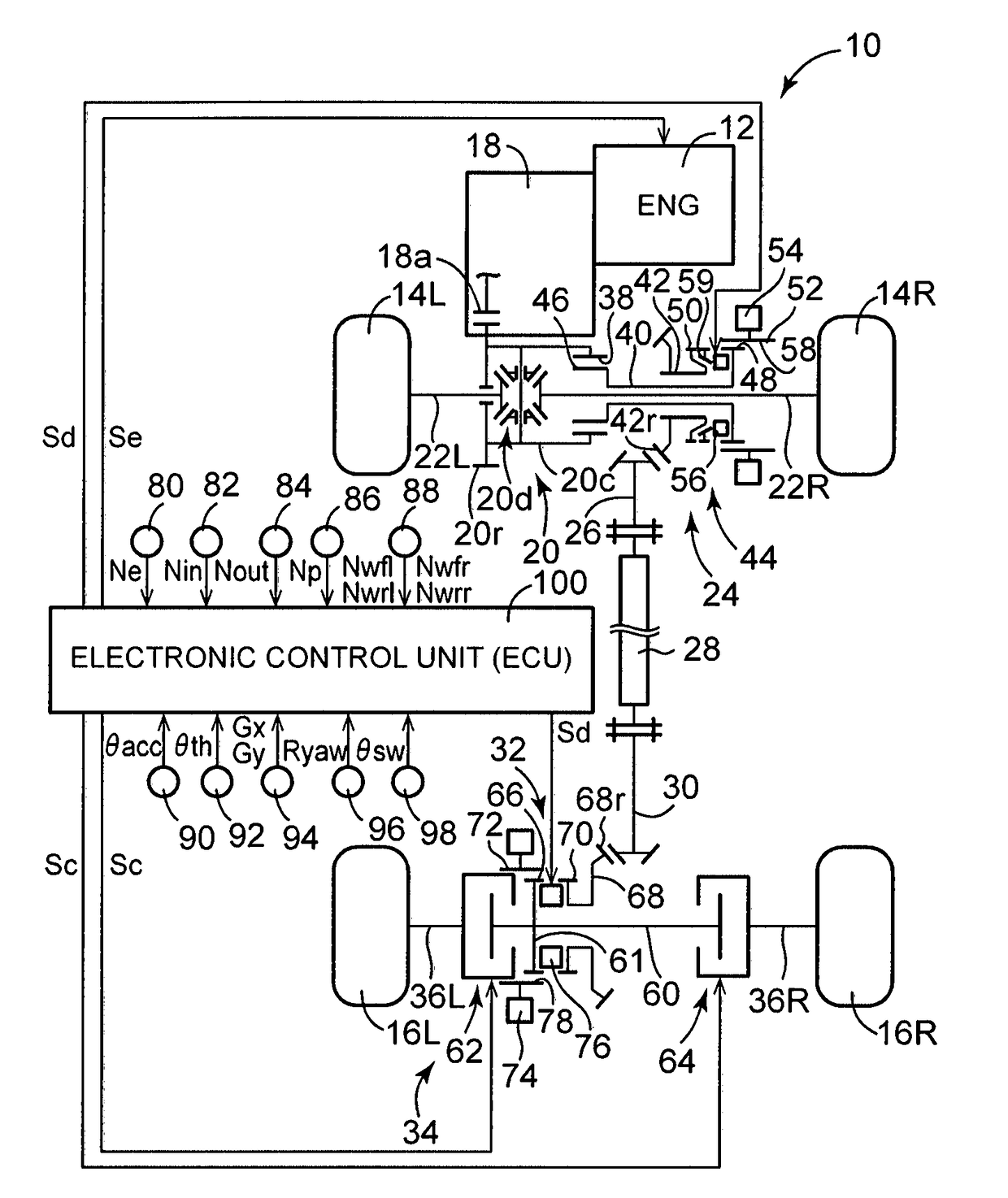
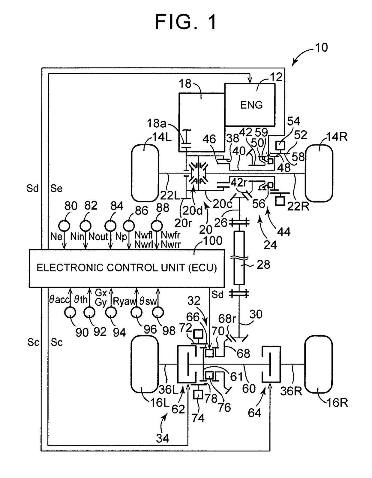
[0026]FIG. 1 is a skeleton diagram showing a schematic configuration of a four wheel drive (i.e. 4WD) vehicle 10 (hereinafter, referred to as a vehicle 10) to which the invention is applied. Also, FIG. 1 is a diagram showing a main part of a control system for various types of control in the vehicle 10. According to FIG. 1, the vehicle 10 is provided with an engine 12, right and left front wheels 14R, 14L (hereinafter, referred to as front wheels 14 if not particularly distinguished), right and left rear wheels 16R, 16L (hereinafter, referred to as rear wheels 16 if not particularly distinguished), a first power transmission path that is a power transmission path between the engine 12 and the front wheels 14 and transmits the power of the engine 12 to the front wheels 14, a second power transmission path that is a power transm...

second embodiment

[0075]Next, the invention will be described. In the following description, like reference numerals will be used to refer to the parts common to the embodiments and description thereof will be omitted.

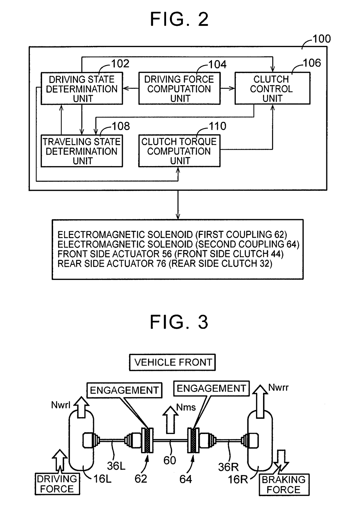
[0076]In the first embodiment described above, the clutch control unit 106 executes the 2WD clutch engagement control by engaging or half-engaging the first coupling 62 and the second coupling 64 at the same time and at an equal clutch torque with the 2WD state being maintained. Instead of this manner in the first embodiment described above, the clutch control unit 106 according to the second embodiment executes the 2WD clutch engagement control by respectively engaging or half-engaging the first coupling 62 and the second coupling 64, with the 2WD state being maintained, based on the deviation between the average rotation speed of the right and left rear wheels 16 and the respective vehicle wheel speeds Nwrr, Nwrl. Even in this case, the differential between the right and left rear whe...


PUM


Abstract

A control device for a four wheel drive vehicle. Differential limitation is applied to both of right and left rear wheels, with 2WD_d state being maintained, by executing two wheel control for engaging or half-engaging a first clutch and a second clutch. As the two wheel drive control is executed, a moment that suppresses the rotation speed difference between the right and left rear wheels acts on the right and left rear wheels even in the 2WD_d state. When the rotation speed difference occurs between the right and left rear wheels, a braking force is allowed to act on the vehicle wheel on the high rotation side and a driving force is allowed to act on the vehicle wheel on the low rotation side through the execution of the two wheel drive control so that a stable moment acts on the vehicle without a transition to a 4WD state.

Description

BACKGROUND OF THE INVENTION[0001]1. Field of the Invention[0002]The invention relates to a control device for a four wheel drive (i.e. 4WD) vehicle that is provided with a disconnection mechanism for the connection / disconnection of a power transmission path for transmitting power of a driving force source to auxiliary driving wheels and right and left clutches disposed in respective power transmission paths to both of the right and left auxiliary driving wheels.[0003]2. Description of Related Art[0004]A 4WD vehicle is widely known that is provided with a disconnection mechanism for the disconnection of a power transmission path for transmitting a part of power of a driving force source transmitted to main driving wheels to auxiliary driving wheels, which become driven wheels during two wheel driving (i.e. 2WD), during 4 wheel drive (i.e. 4WD) and a first clutch and a second clutch disposed in respective power transmission paths to the right and left auxiliary driving wheels. One of ...

Claims


Application Information

Patent Timeline
IPC IPC(8): B60K23/04B60K17/35
CPCB60K23/04B60K17/3515B60Y2300/52B60Y2300/022B60Y2300/42B60K2023/043Y02T10/40
Inventor MAEDA, YOSHINORI
Owner TOYOTA JIDOSHA KK
Why Eureka
Try Eureka