
Electronic control unit and method for compensating for torque steer

a technology of electronic control unit and torque steer, which is applied in the direction of electric steering, power driven steering, vehicle components, etc., can solve the problem that the torque steer that occurs cannot be appropriately reduced

Active Publication Date: 2017-04-27
HL MANDO CORP
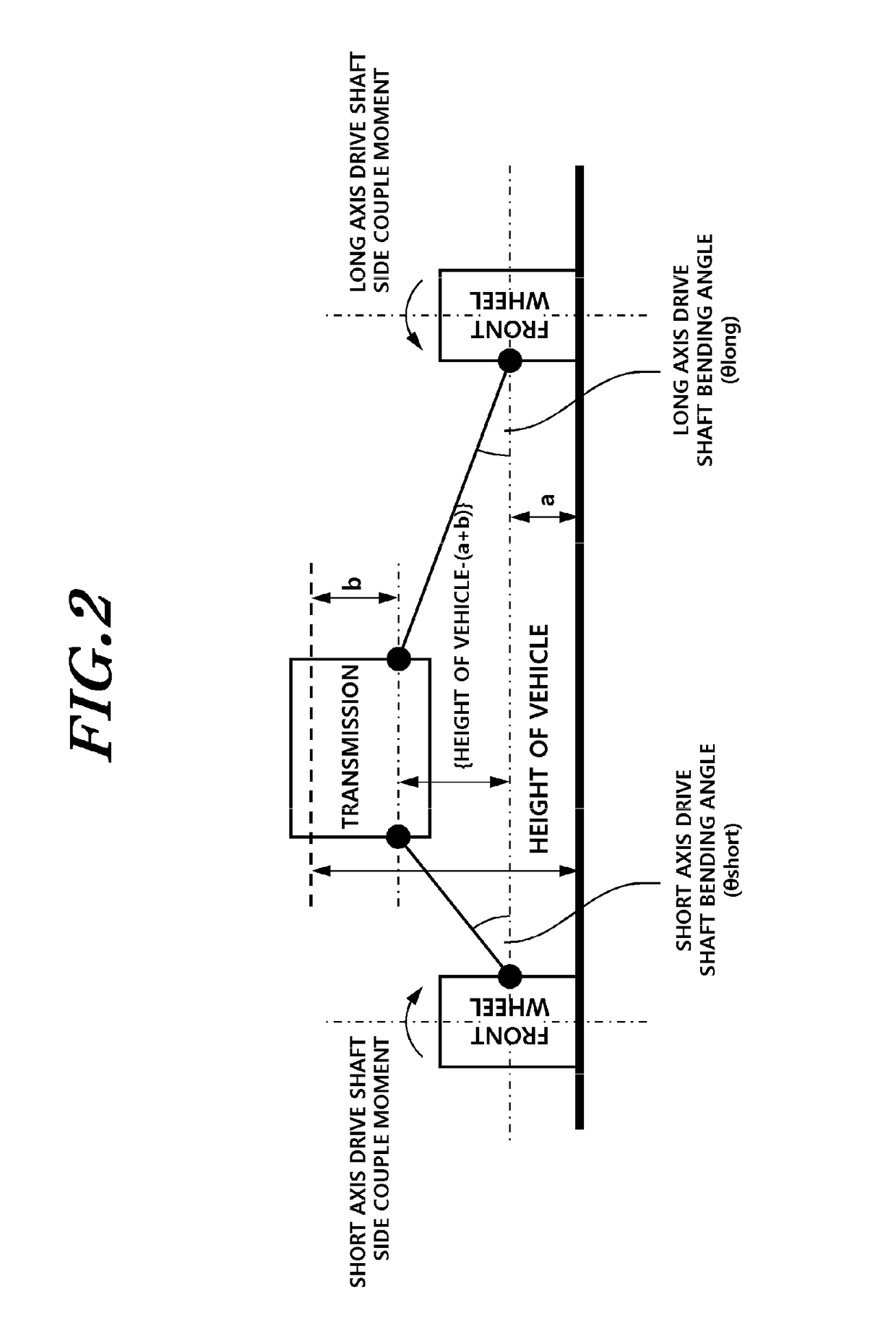
View PDF0 Cites 9 Cited by
  • Summary
  • Abstract
  • Description
  • Claims
  • Application Information

AI Technical Summary

Benefits of technology

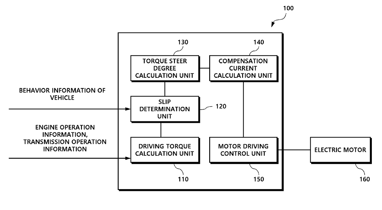
The present invention is about a system that calculates how much torque a vehicle's motor is using while it's driving. This is done by an electronic control unit that takes into account the slip of the vehicle's wheels. The control unit then generates a current to compensate for any changes in the vehicle's stability caused by the torque. As a result, the system can effectively compensate for any "torque steer" that may occur during driving.

Problems solved by technology

Accordingly, if a torque steer is compensated for in an electronic control unit of a power steering system according to the conventional method, the torque steer that occurs cannot actually be appropriately reduced.

Method used


Image

  • Electronic control unit and method for compensating for torque steer
  • Electronic control unit and method for compensating for torque steer
  • Electronic control unit and method for compensating for torque steer

Examples


Embodiment Construction

[0022]Hereinafter, exemplary embodiments of the present invention will be described in detail with reference to the exemplary drawings. In the description of the elements of the present invention, terms “first”, “second”, “A”, “B”, “(a)”, “(b)” and the like may be used. These terms are merely used to distinguish one structural element from other structural elements, and a property, an order, a sequence and the like of a corresponding structural element are not limited by the term. It should be noted that if it is described in the specification that one component is “connected,”“coupled” or “joined” to another component, a third component may be “connected,”“coupled,” and “joined” between the first and second components, although the first component may be directly connected, coupled or joined to the second component.

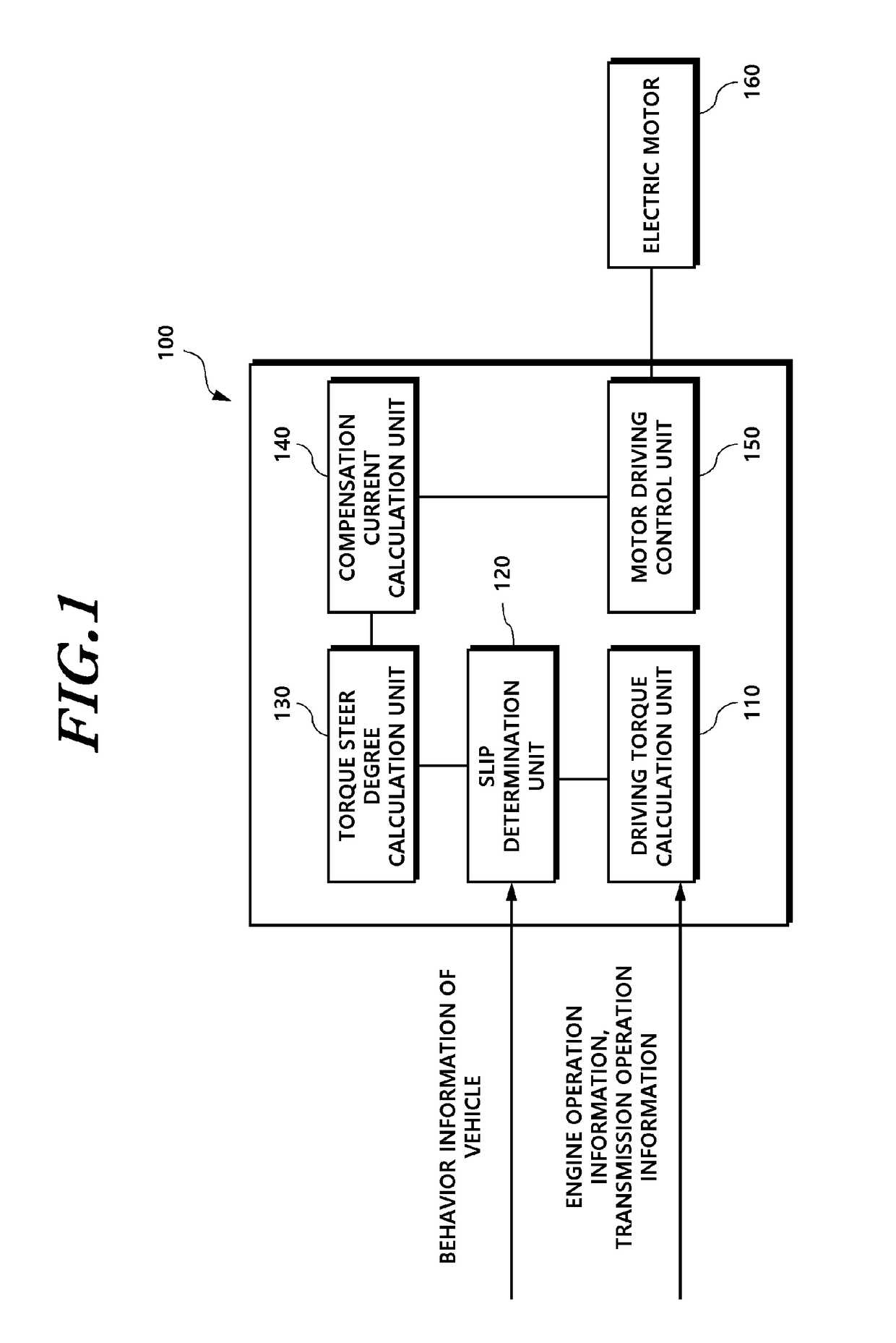
[0023]FIG. 1 is a block diagram schematically illustrating a configuration of an electronic control unit according to an embodiment of the present invention.

[0024]An ele...


PUM


Abstract

The present invention relates to an electronic control unit and a method for compensating for a torque steer. The electronic control unit includes: a driving torque calculation unit that calculates a drive shaft driving torque value using engine operation information and transmission operation information; a torque steer degree calculation unit that calculates the actual driving torque value of a vehicle based on the drive shaft driving torque value, and calculates a torque steer degree by using the actual driving torque value; a compensation current calculation unit that calculates a torque steer compensation current value that compensates for the torque steer using the torque steer degree; and a motor driving control unit that calculates a basic control current value using a steering angle and a steering torque value, calculates the final control current value by adding the torque steer compensation current value to the basic control current value, and generates a control current according to the final control current value in order to supply the control current value to an electric motor.

Description

BACKGROUND OF THE INVENTION[0001]1. Field of the Invention[0002]The present invention relates to an electronic control unit and a method for compensating for a torque steer.[0003]2. Description of the Prior Art[0004]In general, the phenomenon in which the body shell of a vehicle is tilted to one side as a result of a difference between the driving forces of the left and right wheels when the vehicle abruptly starts is called a torque steer phenomenon.[0005]The causes of the torque steer include the difference between the lengths of the left and right drive shafts and the difference between the bending angles of the left and right drive shafts.[0006]The method of solving the torque steer includes a method of adding an intermediate shaft to a short drive shaft in order to make the lengths of the drive shafts and bending angles the same and also includes a method of compensating for a torque steer by using a power steering system.[0007]Among them, the conventional method of compensatin...

Claims


Application Information

Patent Timeline
IPC IPC(8): B62D6/04B62D5/04
CPCB62D6/04B62D5/0475B62D5/0463B62D7/159B62D6/003
Inventor KO, SANG JIN
Owner HL MANDO CORP
Learn More