Converging flow joint insert system at an intersection between adjacent transitions extending between a combustor and a turbine assembly in a gas turbine engine

a technology of converging flow and insert system, which is applied in the direction of machines/engines, stators, light and heating apparatus, etc., can solve the problems of reducing affecting so as to reduce stress formation and enhance the life of inserts

Inactive Publication Date: 2017-04-27
SIEMENS ENERGY INC
View PDF2 Cites 2 Cited by
  • Summary
  • Abstract
  • Description
  • Claims
  • Application Information

AI Technical Summary

Benefits of technology

[0005]A transition duct system for routing a gas flow from a combustor to the first stage of a turbine section in a combustion turbine engine, wherein the transition duct system includes one or more converging flow joint inserts forming a trailing edge at an intersection between adjacent transition duct is disclosed. The transition duct system may include a transition duct having an internal passage extending between an inlet to an outlet and may expel gases into the first stage...

Problems solved by technology

The forces and heat involved diminished material properties causing crac...

Method used


Image

  • Converging flow joint insert system at an intersection between adjacent transitions extending between a combustor and a turbine assembly in a gas turbine engine
  • Converging flow joint insert system at an intersection between adjacent transitions extending between a combustor and a turbine assembly in a gas turbine engine
  • Converging flow joint insert system at an intersection between adjacent transitions extending between a combustor and a turbine assembly in a gas turbine engine

Examples


Embodiment Construction

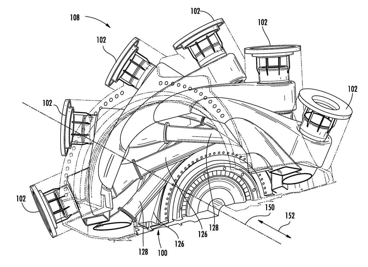
[0065]As shown in FIGS. 11-46, a transition duct system 100 for routing a gas flow from a combustor 102 to the first stage 104 of a turbine section 106 in a combustion turbine engine 108, wherein the transition duct system 100 includes one or more converging flow joint inserts 120 forming a trailing edge 122 at an intersection 124 between adjacent transition duct 126, 128 is disclosed. The transition duct system 100 may include a transition duct 126 having an internal passage 130 extending between an inlet 132 to an outlet 134 and may expel gases into the first stage turbine 114 with a tangential component. The converging flow joint insert 120 may be contained within a converging flow joint insert receiver 136 and disconnected from the transition duct bodies 126, 128 by which the converging flow joint insert 120 is positioned. Being disconnected on side surfaces eliminates stress formation within the converging flow joint insert 120, thereby enhancing the life of the insert 120. The...


PUM


Abstract

A transition duct system for routing a gas flow from a combustor to the first stage of a turbine section in a combustion turbine engine, wherein the transition duct system includes one or more converging flow joint inserts forming a trailing edge at an intersection between adjacent transition ducts is disclosed. The transition duct system may include a transition duct having an internal passage extending between an inlet to an outlet and may expel gases into the first stage turbine with a tangential component. The converging flow joint insert may be contained within a converging flow joint insert receiver and disconnected from the transition duct bodies by which the converging flow joint insert is positioned. Being disconnected eliminates stress formation within the converging flow joint insert, thereby enhancing the life of the insert. The converging flow joint insert may be removable such that the insert can be replaced once worn beyond design limits.

Description

STATEMENT REGARDING FEDERALLY SPONSORED RESEARCH OR DEVELOPMENT[0001]Development of this invention was supported in part by the United States Department of Energy, Advanced Turbine Development Program, Contract No. DE-FC26-05NT42644. Accordingly, the United States Government may have certain rights in this invention.FIELD OF THE INVENTION[0002]This invention is directed generally to gas turbine engines, and more particularly to transition ducts for routing gas flow from combustors to the turbine section of gas turbine engines.BACKGROUND OF THE INVENTION[0003]In conventional gas turbine engines, as shown in FIG. 1, combustion gases created within a combustor 10 are passed to a turbine assembly via a plurality of transition ducts 12. In many conventional systems, the transition ducts 12 extended longitudinally without any offset in a circumferential direction. A row of first stage vanes 14 were used to turn the combustion exhaust gases before being passed to the row one turbine blades...

Claims


Application Information

Patent Timeline
IPC IPC(8): F01D9/02F01D9/06F01D5/02
CPCF05D2260/20F01D9/023F05D2220/32F01D9/065F01D5/02F02C3/14F05D2250/25F23R3/425F01D9/00F01D9/02F01D9/047F01D25/28F02C7/20F05D2240/10F05D2260/94F05D2260/941F23R3/002F23R3/46F23R3/60F23R2900/00005
Inventor WIEBE, DAVID J.CARLSON, ANDREWSTOKER, KYLE C.
Owner SIEMENS ENERGY INC
Why Eureka
Try Eureka