Room condition monitoring system

a monitoring system and room technology, applied in the field of automatic building management systems and communication networks, can solve the problems of difficult and expensive interfacing between a bms and other devices, bacnet ms/tp networks are relatively slow, and the distance gained

Active Publication Date: 2017-04-27
SETRA SYST
View PDF1 Cites 58 Cited by
  • Summary
  • Abstract
  • Description
  • Claims
  • Application Information

AI Technical Summary

Problems solved by technology

Unfortunately, because of the variety of communications protocols, legacy devices and the expense of running new wiring for local devices to remote sensors, interfacing between a BMS and other devices can be difficult and expensive.
Compared to an Ethernet carried network traffic the BACnet MS / TP networks are relatively slow; however, the attractiveness of this type of network is the long distance gained between network connections.
The connectivity of a BACnet / IP network uses the same equipment as standard IT equipment; however, current routers are not programmed to understand the BACnet / IP network traffic.
Another limitation of the existing room condition monitors resides in the user interface.
However, this technology presents a few problems, namely resistive touch screens do not allow advanced gesturing to facilitate easier user interface and they are not compatible with gloved hands to be used in critical applications.
Existing resistive touch screens are generally limited to a one touch point on the screen.
With resistive or standard capacitive display technology the end users need to either take off his / her protective gloves or use a stylus, which may become lost if not attached somehow to the monitor.
In addition, resistive touch screens are often times damaged due to relatively soft polyester films as the top layer.

Method used


Image

  • Room condition monitoring system
  • Room condition monitoring system
  • Room condition monitoring system

Examples


Embodiment Construction

[0028]For the purposes of promoting an understanding of the principles and operation of the invention, reference will now be made to the embodiments illustrated in the drawings and specific language will be used to describe the same. It will nevertheless be understood that no limitation of the scope of the invention is thereby intended, such alterations and further modifications in the illustrated device, and such further applications of the principles of the invention as illustrated therein being contemplated as would normally occur to those skilled in the art to which the invention pertains.

[0029]It is important to an understanding of the present invention to note that all technical and scientific terms used herein, unless defined herein, are intended to have the same meaning as commonly understood by one of ordinary skill in the art. The techniques employed herein are also those that are known to one of ordinary skill in the art, unless stated otherwise. For purposes of more clea...


PUM

PropertyMeasurementUnit
volumeaaaaaaaaaa
interior volumeaaaaaaaaaa
pressureaaaaaaaaaa

Abstract

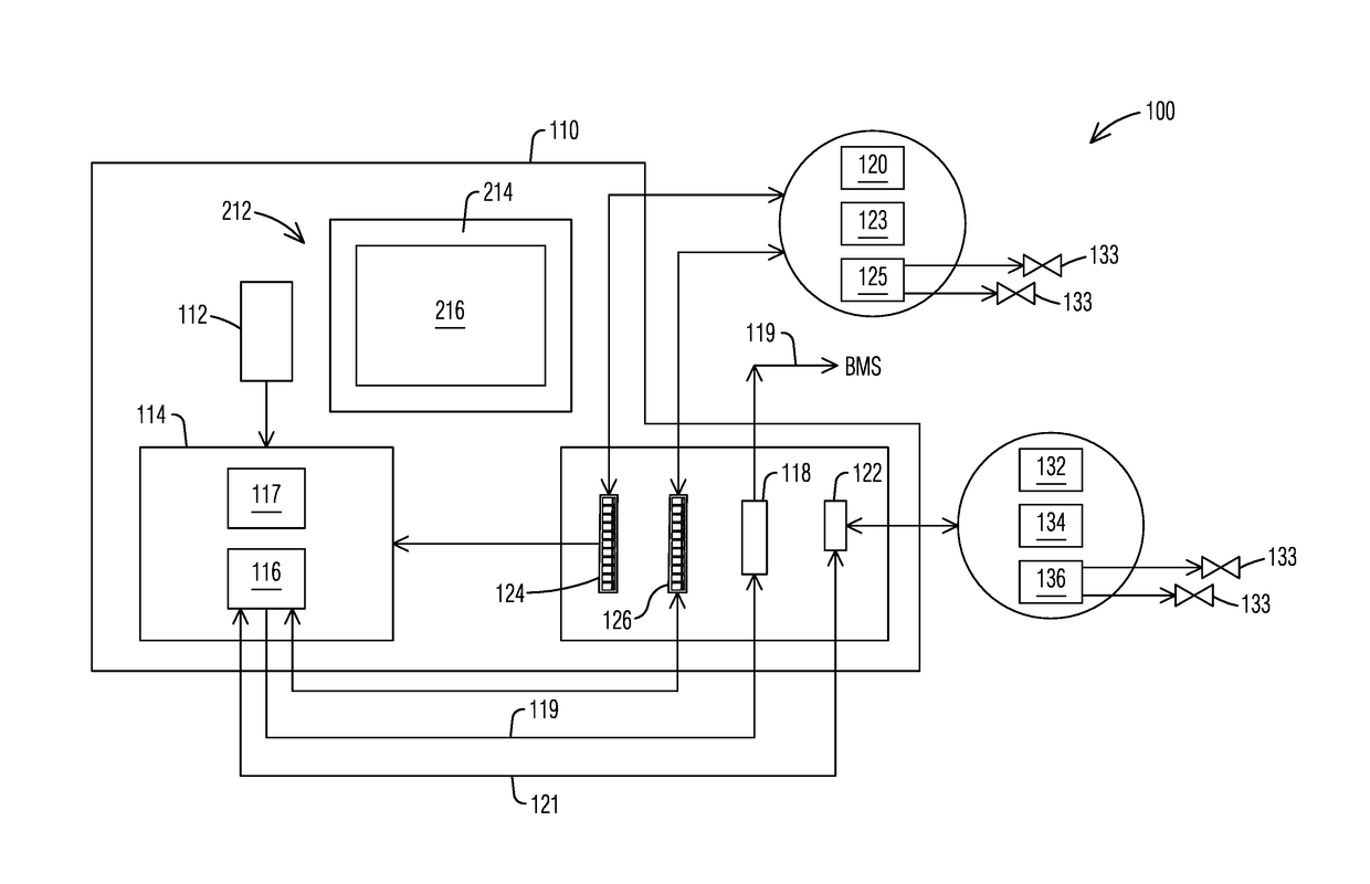
A room condition monitor (RCM) that includes a processor with an embedded router software object that is in signal communication with a first communication connector including BACnet / IP interface for the transmission receipt of data packages over a building management system (BMS) communication network according to a BACnet / IP protocol. The RCM also includes a room condition sensor for detecting a room condition. In addition, the RCM includes a projected capacitive LCD screen display to display information regarding the detected room condition, or other building information associated with the BMS. A second communication connector with a second network protocol interface is provided for communication with network legacy devises through the RCM router.

Description

CROSS-REFERENCE TO RELATED APPLICATIONS[0001]This application claims the benefit of prior U.S. Provisional Application No. 62 / 244,596 filed Oct. 21, 2015, the content of which is hereby incorporated by reference.FIELD OF THE INVENTION[0002]This invention relates generally to automated building management systems and communication networks associated with such systems. This invention is also related to room condition monitoring systems that are components of a building management system.BACKGROUND OF THE INVENTION[0003]Building Management Systems (BMS) or Building Automation Systems (BAS) are computerized control systems installed in buildings for controlling and monitoring a building's mechanical and electrical equipment such as ventilation, lighting, power systems, fire systems, and security systems.[0004]A BMS typically includes a communication network including software and hardware systems networked to control and monitor various parameters of a building's operation. The softwar...

Claims


Application Information

Patent Timeline
Patent Type & Authority Applications(United States)
IPC IPC(8): F24F11/00F24F11/02G01K1/02G01L19/08G01L13/00
CPCF24F11/0086G01L19/086G01L13/00G01K1/024F24F11/0012F24F2011/0061F24F11/02G05B19/048G05B2219/2614F24F2011/0091F24F2011/0042F24F11/0015G05B2219/23258G05B2219/25168F24F2110/10F24F11/30F24F11/523F24F11/64
Inventor GROSSHART, PAUL FRANCISPINTO, GINO AMAROBEISHLINE, ERIC CHRISTOPHERBAROT, SUNILBOURBEAU, KEVINBATISTA, ANTHONY T.HENRY, SHAWN OSCARROGERS, BRANDON THOMASMANNING, II, BERNARD A.
Owner SETRA SYST
Why Eureka
Try Eureka