Optical Design of a Light Field Otoscope

a technology of optical design and otoscope, which is applied in the field of light field otoscopes, can solve the problems of reducing the ability to assess slight reducing the ability to assess small differences in shape and color, and reducing the quantitative measurement of 3d shape or color of imaging sensors

Inactive Publication Date: 2017-05-04
RICOH KK
View PDF22 Cites 9 Cited by
  • Summary
  • Abstract
  • Description
  • Claims
  • Application Information

AI Technical Summary

Problems solved by technology

Traditional otoscopes severely limit the field-of-view (FOV) and magnification of the TM.
This creates monocular tunnel vision for the user, which reduces the ability to assess slight differences in shape and color.
New digital otoscopes can provide high-resolution large FOV images, but their current imaging sensors do not provide quantitative measurements of 3D shape or color.
Optics used in current otoscopes and otoscopes have parameters that result in low-accuracy light field 3D reconstructions.
Current optics within otoscopes and otoscopes contain very small and / or inaccessible apertures, which makes insertion of spectral filters impractical.

Method used


Image

  • Optical Design of a Light Field Otoscope
  • Optical Design of a Light Field Otoscope
  • Optical Design of a Light Field Otoscope

Examples


example optical design 1

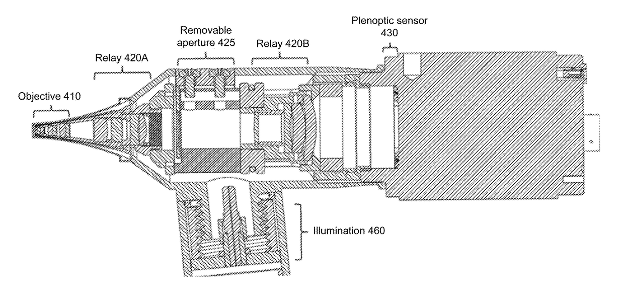
[0051]FIGS. 4A-4D illustrate an example design for a light field otoscope. FIG. 4A shows the entire optical train. This design includes three lens groups: an objective lens group 410 and two relay lens groups 420A, 420B. FIG. 4B is a ray trace of the objective 410. The objective lens group 410 contains a pupil plane P1 towards the front of the objective lens group, so that object-space NA and FOV are maximized while reducing vignetting. In this example, the pupil plane P1 is near the front of the front lens of the objective lens group 410. An image is formed at the rear of the objective lens at image plane I1. Chief rays in the image-space are near telecentric, creating a distant exit pupil that is re-imaged by the following relay lens group 420A. A working distance of 15-25 mm is determined by anatomical constraints of the ear canal. The FOV of 10-20 mm at nominal working distance is selected to image the TM and surrounding ear canal. The overall size of the lens group is constrain...

example optical design 2

[0060]FIGS. 5A-5B illustrate another design for the objective lens group of a light field otoscope. The rest of the design is based on the same principles as shown in FIGS. 4A-4D. FIG. 5A is a ray trace through the objective lens group 510. This design consists of two lens groups, which are separated by a physical aperture. The first negative lens group 512 is a meniscus lens, which collimates the incident light rays into a pupil P1. The objective lens group 510 contains a pupil plane P1 towards the front of the objective lens group, so that object-space NA and FOV are maximized while reducing vignetting. In this example, the pupil plane P1 is near the back of the front lens of the objective lens group 510. The second positive lens group 516 consists of two achromatic doublets, which bend light rays and form an image at an intermediate plane I1. As in the design of FIG. 4, the resultant intermediate image is then relayed to the plenoptic sensor by two relay lens groups, which are no...


PUM


Abstract

Designs for a light field otoscope are disclosed. An example light field otoscope includes an objective lens group, relay optics and a plenoptic sensor (e.g., microlens array and sensor array). The objective lens group images an interior of a human ear and is characterized by a pupil plane and an image plane. The relay optics is positioned between the objective lens group and the plenoptic sensor. It relays the image plane to the microlens array and relays the pupil plane to the sensor array.

Description

CROSS-REFERENCE TO RELATED APPLICATION(S)[0001]This application claims priority under 35 U.S.C. §119(e) to U.S. Provisional Patent Application Ser. No. 62 / 247,343, “Optical Design of a Light Field Otoscope,” filed Oct. 28, 2015. The subject matter of all of the foregoing is incorporated herein by reference in their entirety.BACKGROUND[0002]1. Field of the Invention[0003]This disclosure relates generally to light field otoscopes.[0004]2. Description of Related Art[0005]An otoscope is an optical imaging device used to view and diagnose disease in the middle ear. Clinicians use image features such as color, translucency, and three-dimensional (3D) shape of the tympanic membrane (TM) for diagnosis. Traditional otoscopes severely limit the field-of-view (FOV) and magnification of the TM. This creates monocular tunnel vision for the user, which reduces the ability to assess slight differences in shape and color. New digital otoscopes can provide high-resolution large FOV images, but their...

Claims


Application Information

Patent Timeline
Patent Type & Authority Applications(United States)
IPC IPC(8): A61B1/227A61B1/04G02B7/02A61B1/00G02B3/00G02B13/00
CPCA61B1/227G02B3/0006G02B13/0095G02B5/20A61B1/0019A61B1/04G02B7/021A61B1/00163A61B1/05A61B1/0646A61B1/00096A61B1/042G02B9/60G02B13/22G02B23/243G02B23/2446G02B27/0075G02B9/12
Inventor BEDARD, NOAHTOSIC, IVANAGAO, LIANG
Owner RICOH KK
Why Eureka
Try Eureka