Additive manufacturing apparatus and a flow device for use with such apparatus

a manufacturing apparatus and flow device technology, applied in additive manufacturing, manufacturing tools, manufacturing environment conditioning, etc., can solve the problems of porosity and strength variation in position, and achieve the effect of reducing turbulen

Active Publication Date: 2017-05-04
RENISHAW PLC
View PDF4 Cites 28 Cited by
  • Summary
  • Abstract
  • Description
  • Claims
  • Application Information

AI Technical Summary

Benefits of technology

[0006]In use, the jet of gas (or so called “Coand{hacek over (a)} jet”) directed over the Coand{hacek over (a)} surface is pulled towards and travels along the surface by virtue of the Coand{hacek over (a)} effect, which, in turn, generates suction that draws additional gas into the space adjacent the surface. Typically, the Coand{hacek over (a)} surface turns away from a direction of the jet. Use of such a device to generate gas flow through the chamber may improve the entrapment and transport of condensate from the build chamber relative to an air flow generated by blowing gas through the chamber. Such a device may generate a more uniform gas flow, reducing variation in properties of a build across the build chamber.
[0028]The active gas flow device may comprise at least one opening therein for propelling gas into the build chamber. The opening may generate a jet of gas along a surface of the active flow device. The surface may be a Coand{hacek over (a)} surface. The surface may be a surface that extends parallel to a direction of the jet. Generating a high velocity gas flow along surfaces of the flow device / wiper may reduce turbulence generated from the gas flow intersecting the wiper as the wiper moves across the working surface.

Problems solved by technology

The gas flow rail disclosed therein resulted in positional variation in porosity and strength, which was believed to result from frictional losses as gas travelled along a length of the gas rail.

Method used


Image

  • Additive manufacturing apparatus and a flow device for use with such apparatus
  • Additive manufacturing apparatus and a flow device for use with such apparatus
  • Additive manufacturing apparatus and a flow device for use with such apparatus

Examples


Embodiment Construction

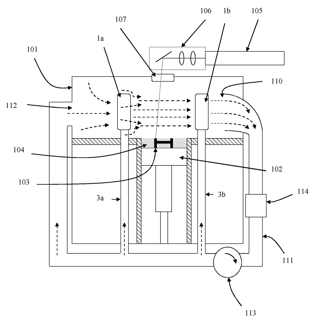
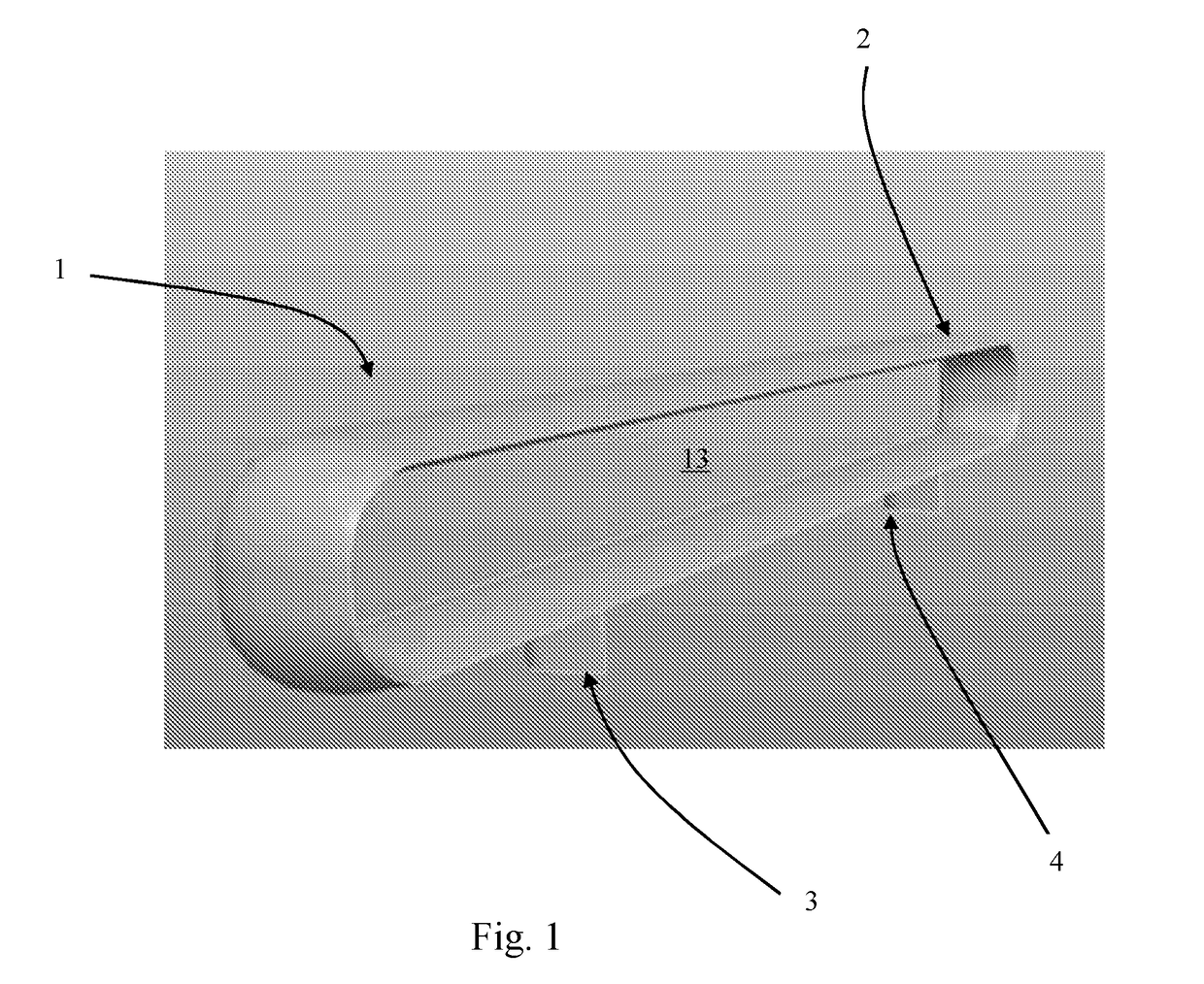
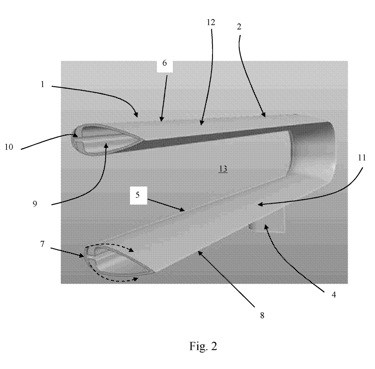
[0037]Referring to FIGS. 1 and 2, a flow device 1 for use in an additive manufacturing apparatus comprises a body 2 that defines an aperture / mouth 13 and legs 3, 4 for supporting the body 2. The aperture / mouth 13 defined by the body 2 has a substantially oval form with a length significantly greater than its width.

[0038]The body 2 comprises a plenum 9 connectable to a pressurised gas source (not shown), for example via a passageway through leg 3 or 4, the plenum 9 connected to openings 5, 6 in the body 2 via a T-shaped internal passageway 10. The confinement of the pressurised gas entering the passageway 10 / openings 5, 6 from the plenum 9 generates a jet of gas at the openings 5, 6.

[0039]The body 2 has a tear-drop shaped cross-section tapering from a broad, upstream end 7 to a narrow, downstream end, in this embodiment, a point 8. The openings 5, 6 are located near the upstream end 7 of the body 2 to direct the jet of gas over an inwardly facing surface 11 and an outwardly facing su...


PUM

PropertyMeasurementUnit
volumeaaaaaaaaaa
shapeaaaaaaaaaa
thicknessaaaaaaaaaa

Abstract

An additive manufacturing apparatus including a build chamber in which an object is built and a flow device. The flow device comprises a body having a Coand{hacek over (a)} surface and a passageway connectable to a pressurised gas source. The passageway has an opening located adjacent to the Coand{hacek over (a)} surface to, in use, direct a jet of gas over the Coand{hacek over (a)} surface. A space adjacent the Coand{hacek over (a)} surface is in fluid communication with the build chamber such that gas drawn into and / or propelled from the space causes gas flow through the build chamber.

Description

FIELD OF INVENTION[0001]This invention concerns additive manufacturing apparatus and a flow device for use in such apparatus. The invention has particular, but not exclusive application, to apparatus for selective laser melting (SLM) and selective laser sintering (SLS).BACKGROUND[0002]Additive manufacturing or rapid prototyping methods for producing components comprise layer-by-layer consolidation of a material, such as a powder material, using a focussed laser beam or an electron beam. In SLM or SLS, a powder layer is deposited in a build chamber and a focussed laser beam is scanned across portions of a powder layer that correspond to a cross-section of the component being constructed such that the powder at the points where the laser scans is consolidated either by sintering or fusion. After consolidation of a layer, a build surface is lowered by a thickness of the newly consolidated layer and a further layer of powder is spread over the surface and consolidated as required. Typic...

Claims


Application Information

Patent Timeline
Patent Type & Authority Applications(United States)
IPC IPC(8): B22F3/105
CPCB22F3/1055B22F2201/50B22F2003/1056B33Y30/00B29C64/268B29C64/371Y02P10/25B22F12/70B22F10/77B22F10/28B22F12/60B22F10/32B22F10/00
Inventor SUTCLIFFE, CHRISTOPHERBROWN, CERI
Owner RENISHAW PLC
Why Eureka
Try Eureka