
System and method for executing gesture based control of a vehicle system

a vehicle system and gesture technology, applied in the field of system and method for executing gesture based control of a vehicle system, can solve the problems of incorrect cumbersome, distracting, etc., and achieve the effect of correct correct determination of driver gestures, and accurate identification of driver gestures

Active Publication Date: 2017-05-04
HONDA MOTOR CO LTD
View PDF2 Cites 21 Cited by
  • Summary
  • Abstract
  • Description
  • Claims
  • Application Information

AI Technical Summary

Benefits of technology

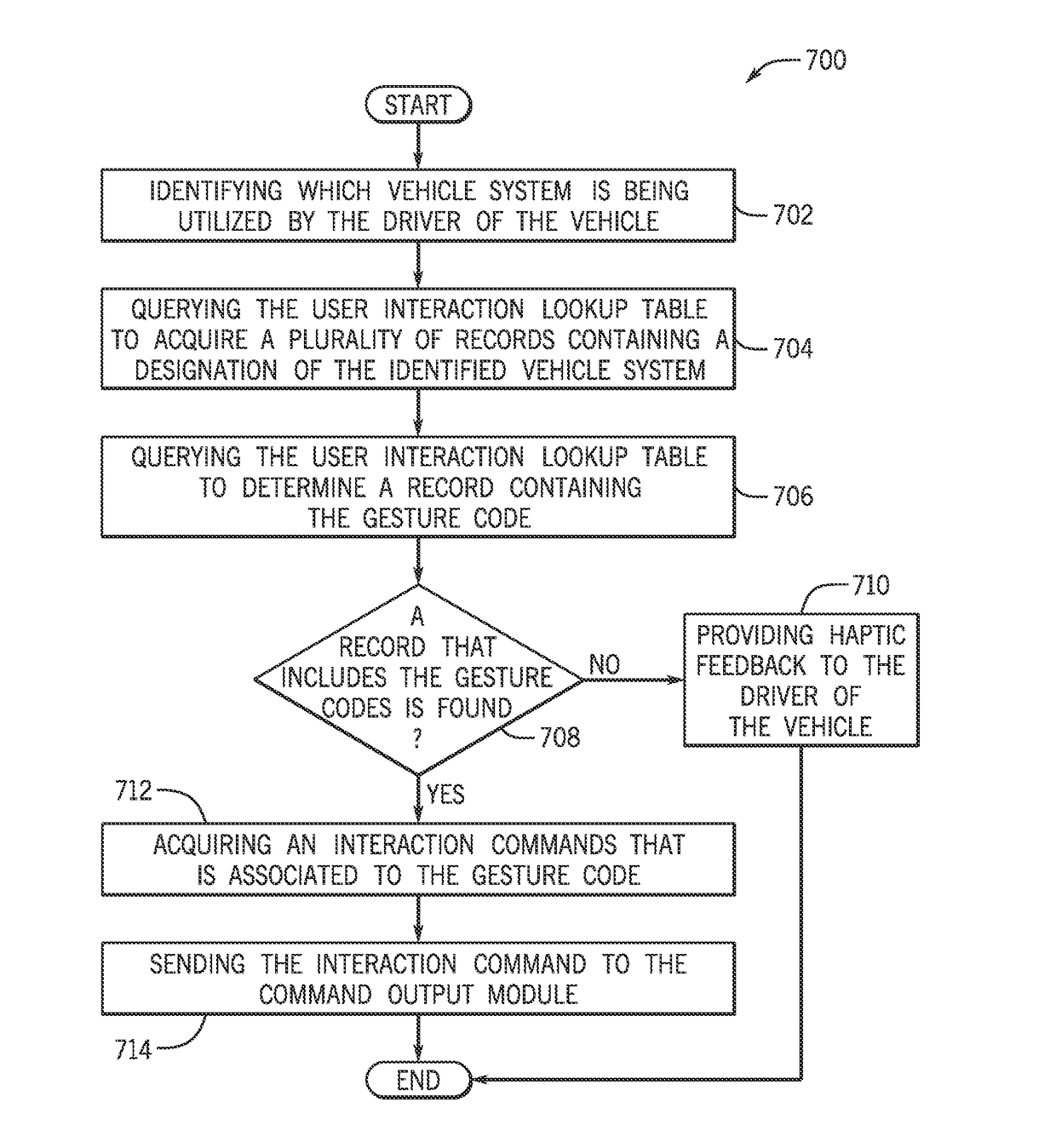
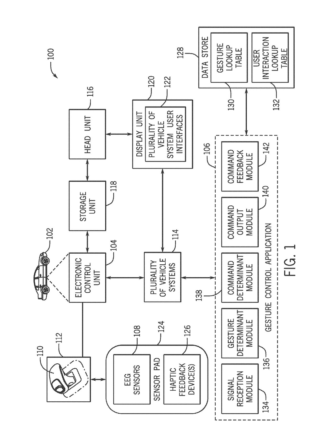
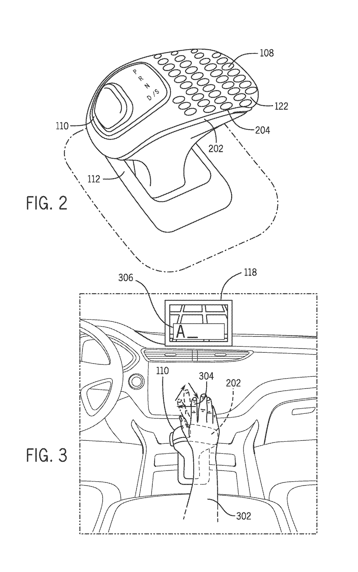
The patent describes a computer-implemented method, system, and computer-readable storage medium for controlling a vehicle system using gestures. The system receives signals from sensors in the gear shift knob and analyzes them to determine which gesture is being made. The system then generates an interaction command based on the determined gesture, which is sent to the vehicle system to execute the command. The technical effect of this system is that it provides a convenient and intuitive way to control the vehicle system without the need for physical contact or remote control devices, improving the driver's experience.

Problems solved by technology

However, it can be cumbersome, distracting, and / or inconvenient for drivers to reach in a specific direction of physical controls or user interface controls on touchscreens to interact with vehicle systems.
However, these systems often have issues correctly determining a driver gestures.
For example, some factors such as poor lighting and / or obstruction of the camera lens can cause these camera based system to incorrectly identify driver gestures.
These issues can require a driver to reenact gestures repeatedly or resume to utilizing physical or user interface controls in order to interact with vehicle systems causing further distraction and inconvenience for the drivers.

Method used


Image

  • System and method for executing gesture based control of a vehicle system
  • System and method for executing gesture based control of a vehicle system
  • System and method for executing gesture based control of a vehicle system

Examples


Embodiment Construction

[0013]The following includes definitions of selected terms employed herein. The definitions include various examples and / or forms of components that fall within the scope of a term and that can be used for implementation. The examples are not intended to be limiting.

[0014]A “bus”, as used herein, refers to an interconnected architecture that is operably connected to other computer components inside a computer or between computers. The bus can transfer data between the computer components. The bus can be a memory bus, a memory controller, a peripheral bus, an external bus, a crossbar switch, and / or a local bus, among others. The bus can also be a vehicle bus that interconnects components inside a vehicle using protocols such as Media Oriented Systems Transport (MOST), Controller Area network (CAN), Local Interconnect Network (LIN), among others.

[0015]“Computer communication”, as used herein, refers to a communication between two or more computing devices (e.g., computer, personal dig...


PUM


Abstract

A method and system for executing gesture based control of a vehicle system that include receiving at least one signal that pertains to at least one muscle movement from sensors disposed within a gear shift knob. The method and system also include determining at least one gesture based on the at least one signal. Additionally, the method and system include determining an interaction command with the vehicle system based on the at least one gesture. The method and system further include outputting the interaction command to the vehicle system.

Description

BACKGROUND[0001]Generally, in order to utilize and control vehicle system features, drivers have must physically interact with vehicle system controls. For example, to utilize a vehicle audio system, drivers of vehicles have to physically interact with physical controls such as knobs, dials, and switches provided on a vehicle console. Alternatively, vehicle systems may include user interface controls that allow drivers to interact with the vehicle systems via a touchscreen displaying the user interface. However, it can be cumbersome, distracting, and / or inconvenient for drivers to reach in a specific direction of physical controls or user interface controls on touchscreens to interact with vehicle systems.[0002]Some camera based systems have been introduced that allow drivers to perform gestures to interact with the vehicle systems. However, these systems often have issues correctly determining a driver gestures. For example, some factors such as poor lighting and / or obstruction of ...

Claims


Application Information

Patent Timeline
Patent Type & Authority Applications(United States)
IPC IPC(8): B60W50/10B60K35/00B60R16/023
CPCB60W50/10B60K2350/1052B60K35/00B60R16/023F16H59/02B60K35/10B60K2360/146B60K2360/1464B60K2360/21G06V40/28G06F3/017G06F3/04883G06T7/20
Inventor LING, CALVINNEHMAD, MICHAEL
Owner HONDA MOTOR CO LTD
Learn More