
Solid rocket motors including flight termination systems, and related multi-stage solid rocket motor assemblies and methods

Active Publication Date: 2017-05-04
NORTHROP GRUMMAN SYST CORP
View PDF8 Cites 7 Cited by
  • Summary
  • Abstract
  • Description
  • Claims
  • Application Information

AI Technical Summary

Benefits of technology

This patent describes a solid rocket motor with a pressure vessel, a solid propellant structure, and a flight termination system. The flight termination system includes a shaped charge that is positioned to ignite the solid propellant structure and reduce the pressure vessel's ability to withstand increases in pressure. The invention also involves a multi-stage rocket motor assembly with a pressure vessel and a flight termination system comprising at least one shaped charge. Additionally, the patent describes a method for destroying a launch vehicle in flight by initiating the shaped charge of the flight termination system to pressurize and weaken the pressure vessel of the solid rocket motor to fragment the solid propellant structure. The technical effect of this patent is to improve the safety and reliability of solid rocket motors and multi-stage rocket motor assemblies.

Problems solved by technology

Such flight termination systems can make a pressurized solid rocket motor non-propulsive, and can break the solid propellant structure of the pressurized solid rocket motor into relatively smaller pieces.
Unfortunately, such flight termination systems do not adequately break up the propellant structures of unpressurized solid rocket motors (e.g., unpressurized stages of a multi-stage rocket motor assembly) into relatively smaller pieces.
Unfortunately, such flight termination systems can be very complicated and can incur undesirable weight penalties and system costs due to the amounts and / or strengths of shaped charges required.
Unfortunately, such flight termination systems can also be very complicated, can be undesirably energetic as a result of the high pressures and energy release effectuated during the pulverization process, and can be insufficient and / or prohibitively expensive to destroy to the solid propellant structures of relatively larger (e.g., longer) solid rocket motors.

Method used


Image

  • Solid rocket motors including flight termination systems, and related multi-stage solid rocket motor assemblies and methods
  • Solid rocket motors including flight termination systems, and related multi-stage solid rocket motor assemblies and methods
  • Solid rocket motors including flight termination systems, and related multi-stage solid rocket motor assemblies and methods

Examples


Embodiment Construction

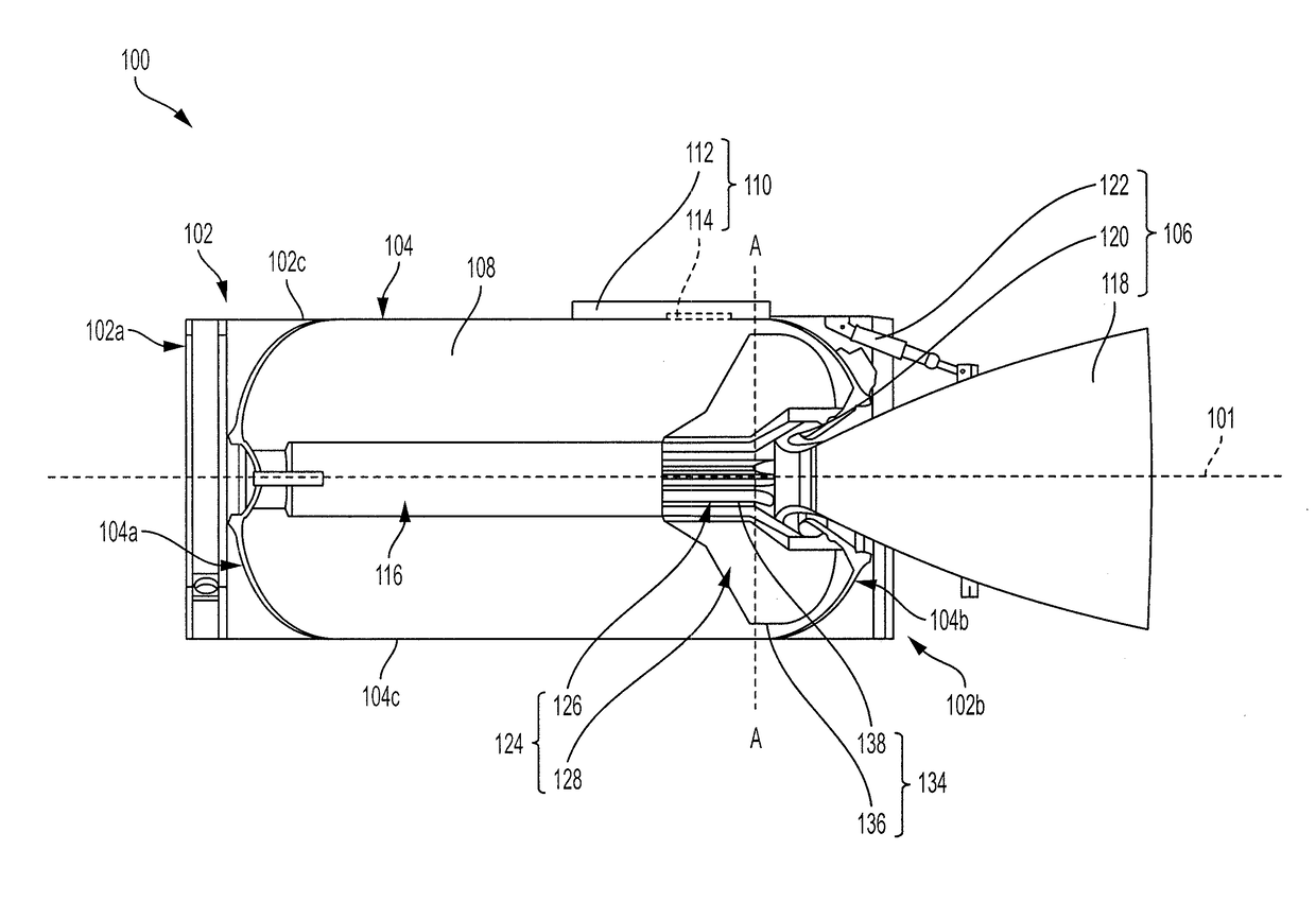
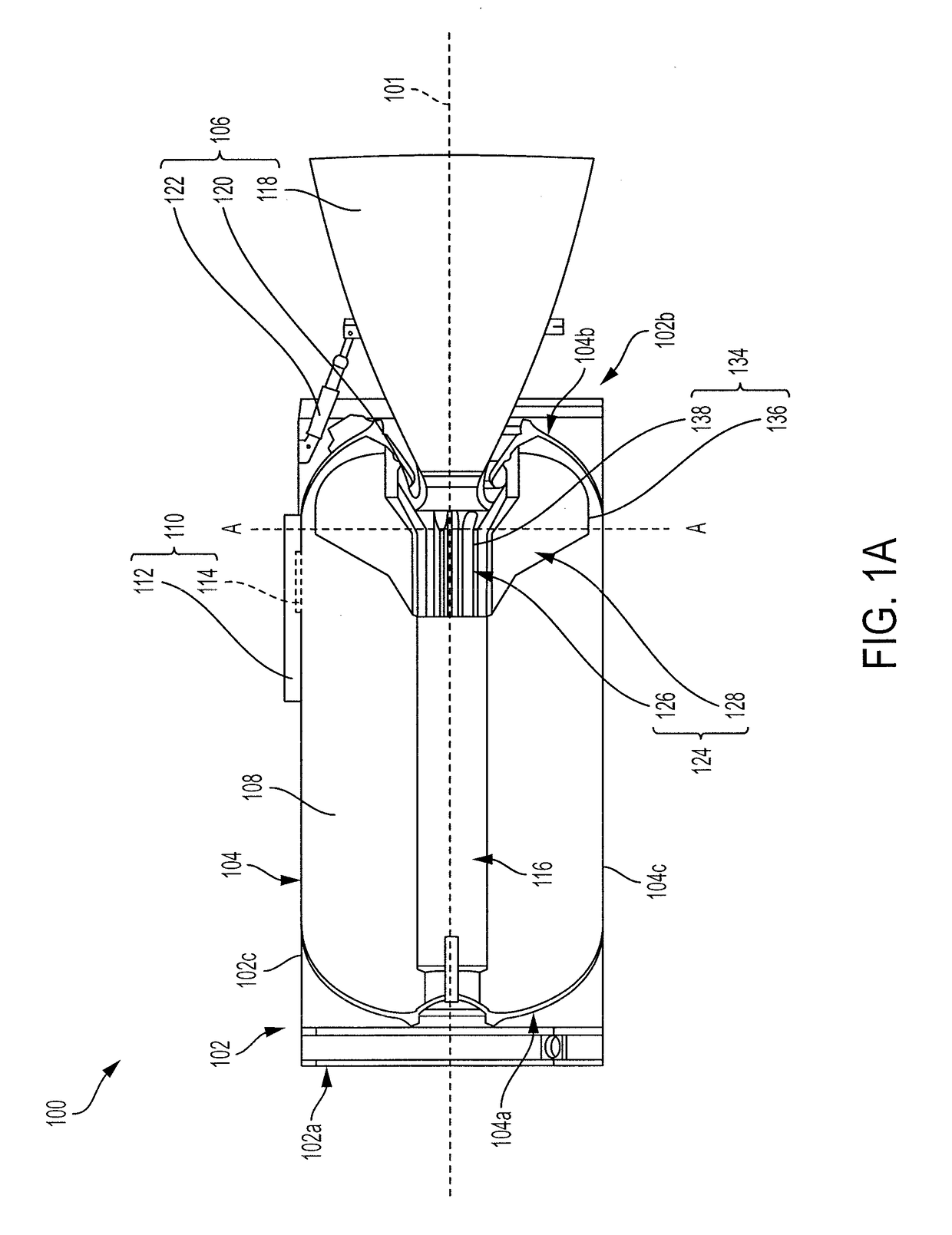
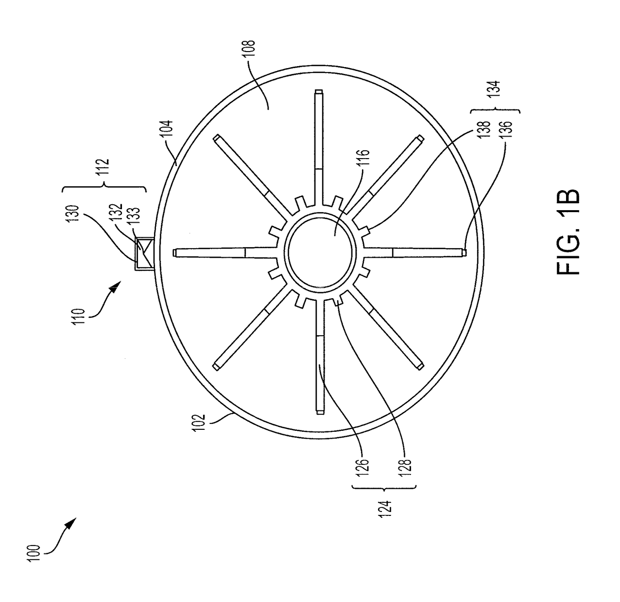
[0013]Solid rocket motors including flight termination systems are disclosed, as are multi-stage rocket motor assemblies, and methods of destroying a launch vehicle in flight. In some embodiments, a solid rocket motor includes a pressure vessel, a solid propellant structure within the pressure vessel, and a flight termination system overlying the pressure vessel. The flight termination system includes at least one shaped charge configured and positioned to produce at least one cutting jet effective to ignite and pressurize the solid rocket motor and also effective to reduce the ability of the solid rocket motor to withstand a change (e.g., increase) in internal pressure. The at least one cutting jet may penetrate (e.g., cut) through portions of the pressure vessel and the solid propellant structure overlying a radial end of an opening (e.g., groove, slot, fin slot, etc.) within the solid propellant structure to ignite an inner portion of the solid propellant structure proximate the ...


PUM


Abstract

A solid rocket motor comprises a pressure vessel, a solid propellant structure within the pressure vessel, and a flight termination system overlying the pressure vessel. The flight termination system comprises a shaped charge configured and positioned to effectuate ignition of an inner portion of the solid propellant structure and a reduction in an ability of the pressure vessel to withstand a change in internal pressure. Another solid rocket motor, a multi-stage rocket motor assembly, and a method of destroying a launch vehicle in flight are also described.

Description

TECHNICAL FIELD[0001]Embodiments of the disclosure relate generally to solid rocket motor design and fabrication. More particularly, embodiments of the disclosure relate to solid rocket motors including flight termination systems, to related multi-stage rocket motor assemblies, and to related methods of destroying a launch vehicle in flight.BACKGROUND[0002]A solid rocket motor generally includes a pressure vessel (e.g., housing), a solid propellant structure (e.g., grain) within the pressure vessel, and at least one nozzle assembly operatively associated with the pressure vessel and the solid propellant structure. In use and operation, the solid propellant structure is ignited (e.g., by an electric or pyrotechnic igniting device), and as it burns it generates combustion products (e.g., exhaust gases) that are expelled through a thrust nozzle of the nozzle assembly as to provide a thrusting force to propel the solid rocket motor. A multi-stage rocket motor assembly may include a plur...

Claims


Application Information

Patent Timeline
IPC IPC(8): F02K9/92F02K9/34F02K9/76
CPCF02K9/92F02K9/34F02K9/763F02K9/38B64G1/52F02K9/08F02K9/10F02K9/26
Inventor KLIGER, JOSEPH J.BRAITHWAITE, PAUL C.LIECHTY, BRIAN C.PATTERSON, DONALD B.
Owner NORTHROP GRUMMAN SYST CORP
Learn More