Infrared transmitting cover sheet

a technology of infrared transmission and cover sheet, applied in the field of colored cover sheet and film, can solve the problems of lack of awareness and knowledge of integration possibilities among architects, lack of solar products designed for building integration, and inability to consider solar energy systems

Inactive Publication Date: 2017-05-04
CSEM CENT SUISSE DELECTRONIQUE & DE MICROTECHNIQUE SA RECH & DEV
View PDF9 Cites 29 Cited by
  • Summary
  • Abstract
  • Description
  • Claims
  • Application Information

AI Technical Summary

Benefits of technology

[0012]To that problem a solution has been found with the invention, which consists in providing the color filter of the invention which may be arranged to a photovoltaic element or photoconversion device. The color filter, defined as an infrared transmitting cover sheet or a cover sheet or a color layer or a sheet, provides a homogeneous colored aspect to elements on which it is arranged. Arranging the infrared transmitting cover sheet of the invention for example in front of infrared photosensitive devices allows to hide from an observer connecting elements, borders or other non-esthetic features and / or colors of the photosensitive parts of the photosensitive devices.

Problems solved by technology

Despite the wide diversity of available solar technologies, solar energy systems are still not considered as main stream technologies in building practice.
One of the reasons of the lack of wide spread use of solar technologies for buildings is the lack of awareness and knowledge of integration possibilities among architects and the lack of solar products designed for building integration.
This approach does not achieve the four mentioned criteria.
It is also expensive, leads to heavy solar elements and does not allow to be easily integrated in a production process.
The drawback of this color filter is that a part of the visible light is transmitted.
The limitation of such approach is that the color appearance effect depends on the incident angle of the incident light beam.
Moreover, the disclosed device completely blocks all visible light making it less suitable for PV applications as it absorbs all the residual transmitted visible.

Method used


Image

  • Infrared transmitting cover sheet
  • Infrared transmitting cover sheet
  • Infrared transmitting cover sheet

Examples


Embodiment Construction

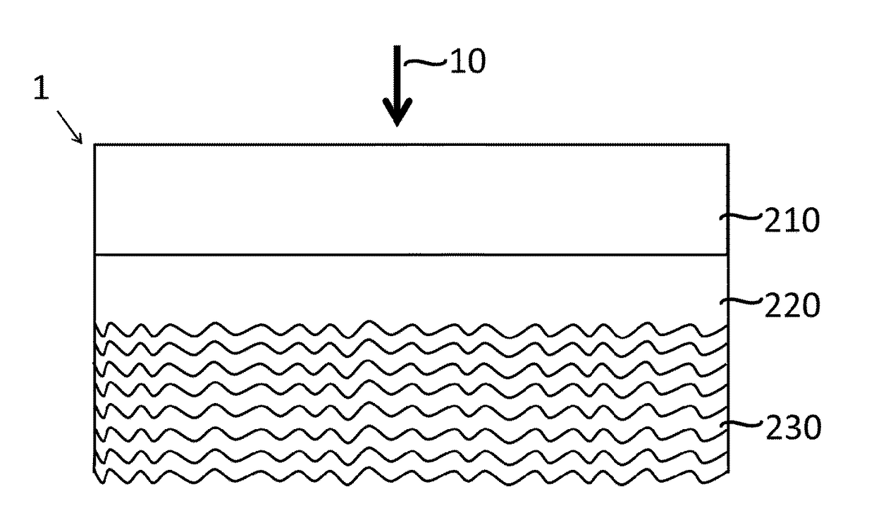
[0068]The invention relates to an infrared transmitting cover sheet 1 intended to receive incident light, comprising:[0069]infrared transmission means arranged to transmit at least 65% of incident infrared light, defined between 700 nm and 2000 nm, through said infrared transmitting cover sheet, the transmission of 65% being a mean value integrated over the wavelength range between 700 nm and 2000 nm; said transmission is defined as the ratio, expressed in %, of the transmitted and incident near-infrared light.[0070]visible light transmission means arranged to transmit as less as possible incident visible light 10 having wavelengths lower than 600 nm, preferably lower than 650 nm, more preferably lower than 700 nm, excluding the wavelength of 700 nm, through said infrared transmitting cover sheet, said as less as possible transmission being preferably lower than 20%, preferably lower than 15%, and more preferably lower than 10%, said transmission value is defined as an average of th...


PUM

PropertyMeasurementUnit
wavelengthaaaaaaaaaa

Abstract

An infrared transmitting cover sheet for receiving incident light having incident visible light and incident near infrared light. The infrared transmitting cover sheet includes: infrared transmission means arranged to transmit at least 65% of the incident near infrared light, through the infrared transmitting cover sheet, visible light transmission means arranged to transmit as less as possible incident visible light having wavelengths lower than 600 nm, excluding the wavelength of 700 nm, through the infrared transmitting cover sheet, and reflection means arranged to reflect a portion of the incident visible light to the side of the incident light.

Description

TECHNICAL FIELD[0001]The invention relates to the field of colored cover sheets and films. More particularly, the present invention relates to an infrared transmitting cover sheet that may be used in applications wherein near infrared light has to be transmitted by the cover sheet that is positioned in front of an infrared sensitive device.BACKGROUND OF THE INVENTION[0002]Despite the wide diversity of available solar technologies, solar energy systems are still not considered as main stream technologies in building practice. So far most photovoltaic systems are optimized only for efficiency which implies absorbing a maximum number of photons, and hence leading to a dark blue and ideally black color appearance. Most of the photovoltaic cells on the market are crystalline cells with connecting ribbons which have an unaesthetic appearance.[0003]One of the reasons of the lack of wide spread use of solar technologies for buildings is the lack of awareness and knowledge of integration pos...

Claims


Application Information

Patent Timeline
Patent Type & Authority Applications(United States)
IPC IPC(8): G02B5/28G02B5/22F24J2/50G02B5/26H02S40/44G02B5/02G02B1/11
CPCG02B5/281G02B5/0278G02B5/22F24J2/506G02B5/26H02S40/44F24J2/505G02B1/11G02B5/265F24S80/52F24S80/525H02S40/20Y02E10/40Y02E10/50Y02E10/60
Inventor BALLIF, CHRISTOPHEESCARRE PALOU, JORDIPERRET-AEBI, LAURE-EMMANUELLELI, HENGYU
Owner CSEM CENT SUISSE DELECTRONIQUE & DE MICROTECHNIQUE SA RECH & DEV
Why Eureka
Try Eureka