Apparatus and methods for uniform sample clocking

a clocking apparatus and clocking technology, applied in the field of laser systems, can solve the problems of undesirable software remapping operation, inability to meet the high-speed oct system, and inability to meet the requirements of high-speed oct systems,

Active Publication Date: 2009-02-19
VOLCANO CORP
View PDF43 Cites 161 Cited by
  • Summary
  • Abstract
  • Description
  • Claims
  • Application Information

AI Technical Summary

Problems solved by technology

This software remapping operation is undesirable due to decreased phase sensitivity (i.e., amplitude and phase errors introduced in the remapping procedure), image artifacts, computational inefficiency, and the bandwidth needed to record a remapping array [k(t)] for each OCT interferogram [S(t)].
Analog-Digital (“A/D”) converter cards that operate at lower frequencies, i.e. low-speed digitizers, are not practical for the high-speed OCT systems.
Moreover, most high speed A/D converter cards have a tim...

Method used


Image

  • Apparatus and methods for uniform sample clocking
  • Apparatus and methods for uniform sample clocking
  • Apparatus and methods for uniform sample clocking

Examples


Embodiment Construction

[0028]The methods, apparatuses, and systems can be understood more readily by reference to the following detailed description of the methods, apparatuses, and systems, and the accompanying figures.

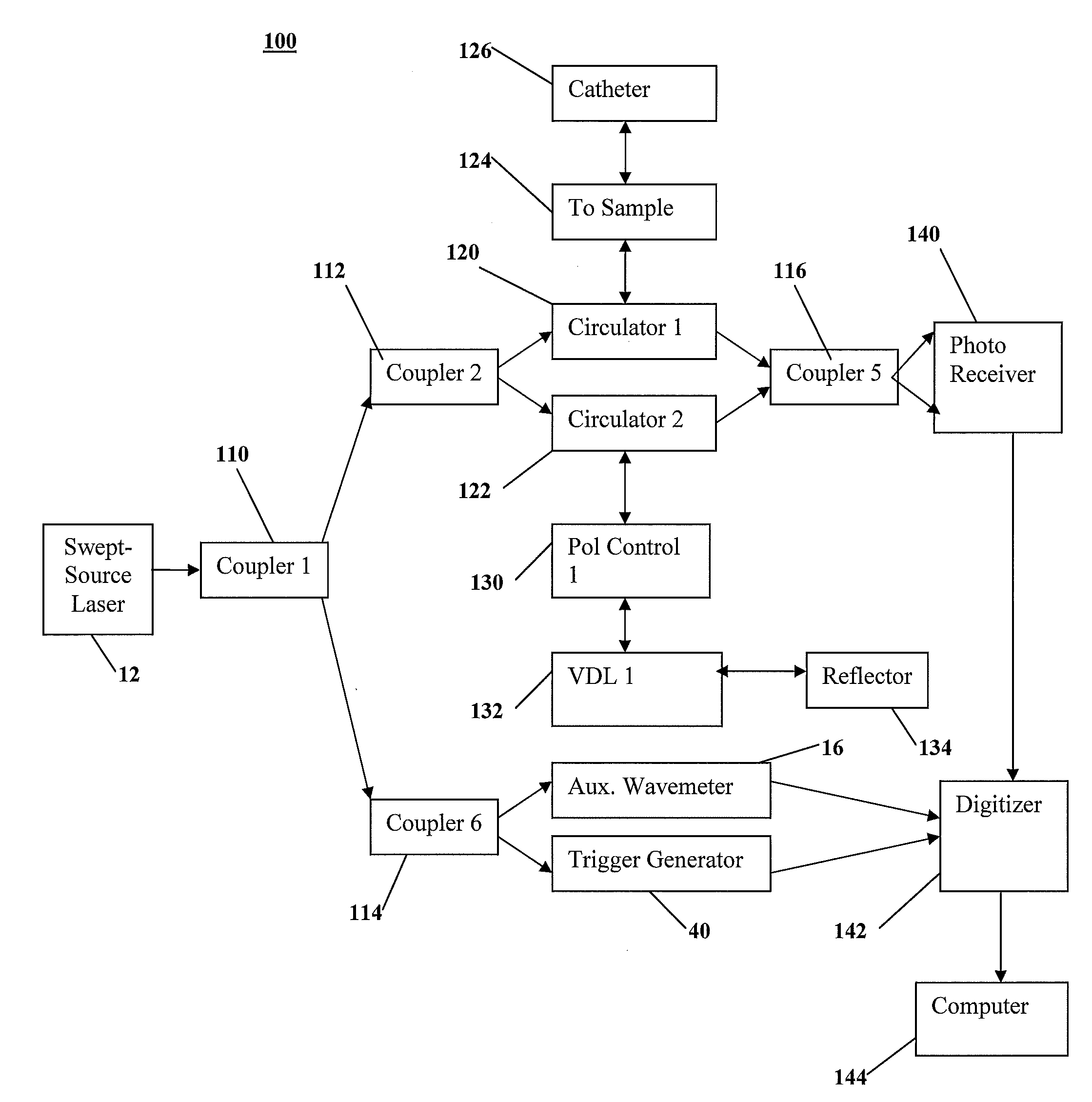
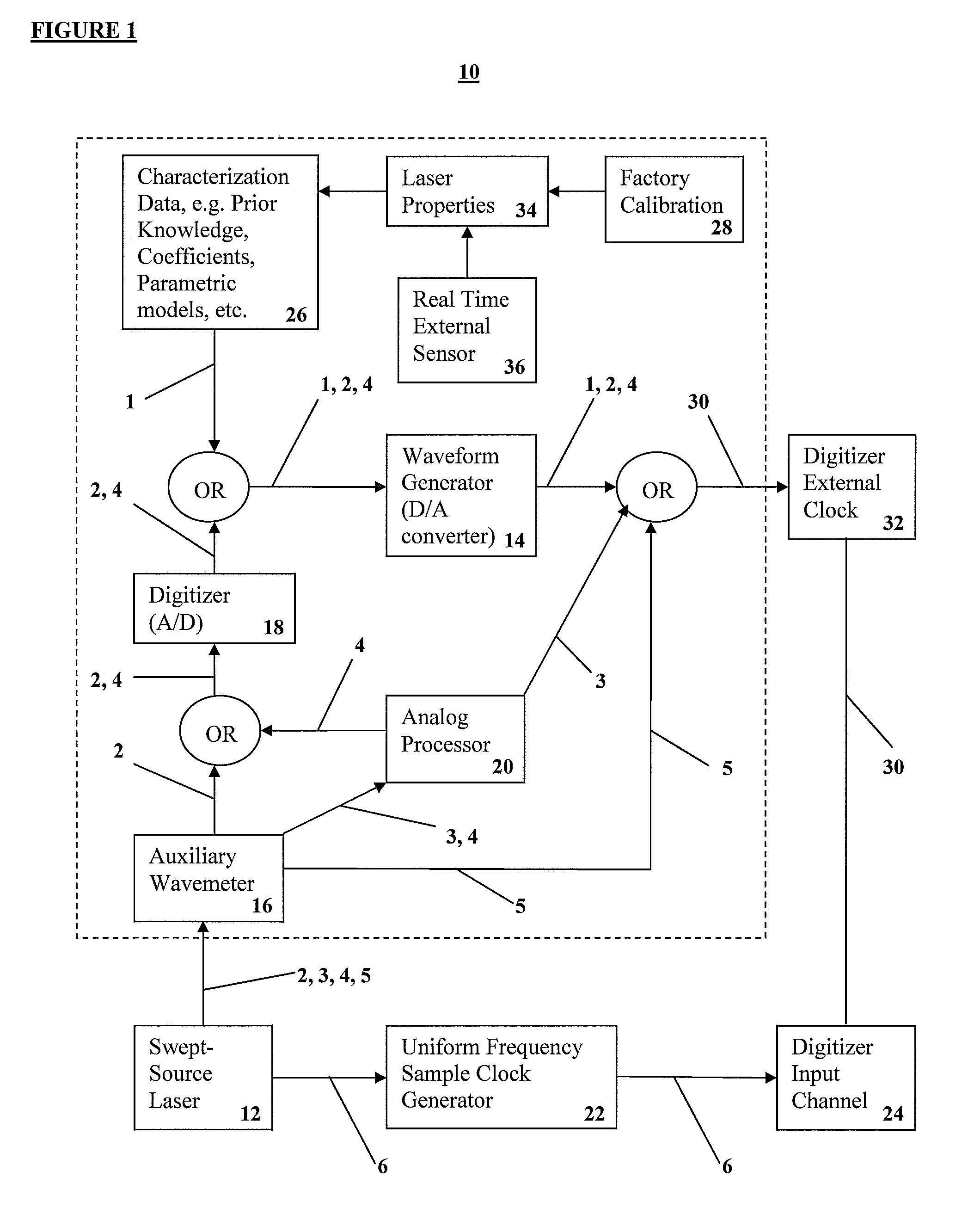
[0029]Generally speaking, a Uniform Frequency Sample Clocking 10 systems and methods for a swept laser source 12 are generally shown in FIG. 1. The Uniform Frequency Sample Clocking 10 comprises at least one Pathway, where some embodiments of the Pathways are generally shown as line arrows in FIG. 1. The line arrows represent electronic or optical coupling elements, such as wires, fibers, and the like. In one embodiment, Uniform Frequency Sample Clocking 10 includes Pathway 1 comprising characterizing 26 the swept laser source 12, creating a digital representation of the waveform based from the characterization data 26, and generating a clock signal 30 using a waveform generator 14 (i.e. a Digital-Analog (“D / A”) converter) to output the clock signal 30 to a digitizer external clock 32. The...


PUM


Abstract

A method and a system for Uniform Frequency Sample Clocking to directly sample the OCT signal with a temporally-non-linear sampling clock derived from a k-space wavemeter on the external sample clock input port of a digitizer.

Description

CROSS-RELATED APPLICATIONS[0001]The present application claims priority to U.S. Provisional Application Ser. No. 60 / 949,467, filed Jul. 12, 2007, incorporated by reference herein.BACKGROUND[0002]The invention is generally related to laser systems, and more particularly related to Optical Coherence Tomography systems and methods.[0003]Optical Coherence Tomography (“OCT”) generates cross sectional imaging of tissues with micro-scale resolution by measuring the echo time delay of backscattered or backreflected light. Fourier Domain OCT (“FD-OCT”) can obtain a high sensitivity and imaging speed by acquiring the optical spectrum of light backscattered from a sample interfered with light from a single stationary reference reflector using an interferometer. Swept-Source OCT (“SS-OCT”), time-encodes the wavenumber (or optical frequency) by rapidly tuning a narrowband light source over a broad optical bandwidth.[0004]The high speed tunable laser sources for SS-OCT exhibit a nonlinear or non-...

Claims


Application Information

Patent Timeline
IPC IPC(8): G01B9/02
CPCA61B5/0066A61B5/0073A61B5/6852A61B5/7257G01M11/3127G01M11/3172G01B2290/25G01B9/02004G01B9/02057G01B9/02091G01B9/02069G01B9/02083G01N21/4795G01B9/02062G01B9/02067
Inventor KEMP, NATHANIEL J.KURANOV, ROMANMCELROY, AUSTIN BRODERICKMILNER, THOMAS E.
Owner VOLCANO CORP
Why Eureka
Try Eureka