Electromagnetic photonic catheter for reducing restenosis

Inactive Publication Date: 2005-11-08
STONE GREGG W +5
View PDF9 Cites 169 Cited by
  • Summary
  • Abstract
  • Description
  • Claims
  • Application Information

AI Technical Summary

Benefits of technology

[0020]In the power range aforementioned, of the infrared source, no cooling medium

Problems solved by technology

In the power range aforementioned, of the infrared source, no cooling medium is

Method used


Image

  • Electromagnetic photonic catheter for reducing restenosis
  • Electromagnetic photonic catheter for reducing restenosis
  • Electromagnetic photonic catheter for reducing restenosis

Examples


Embodiment Construction

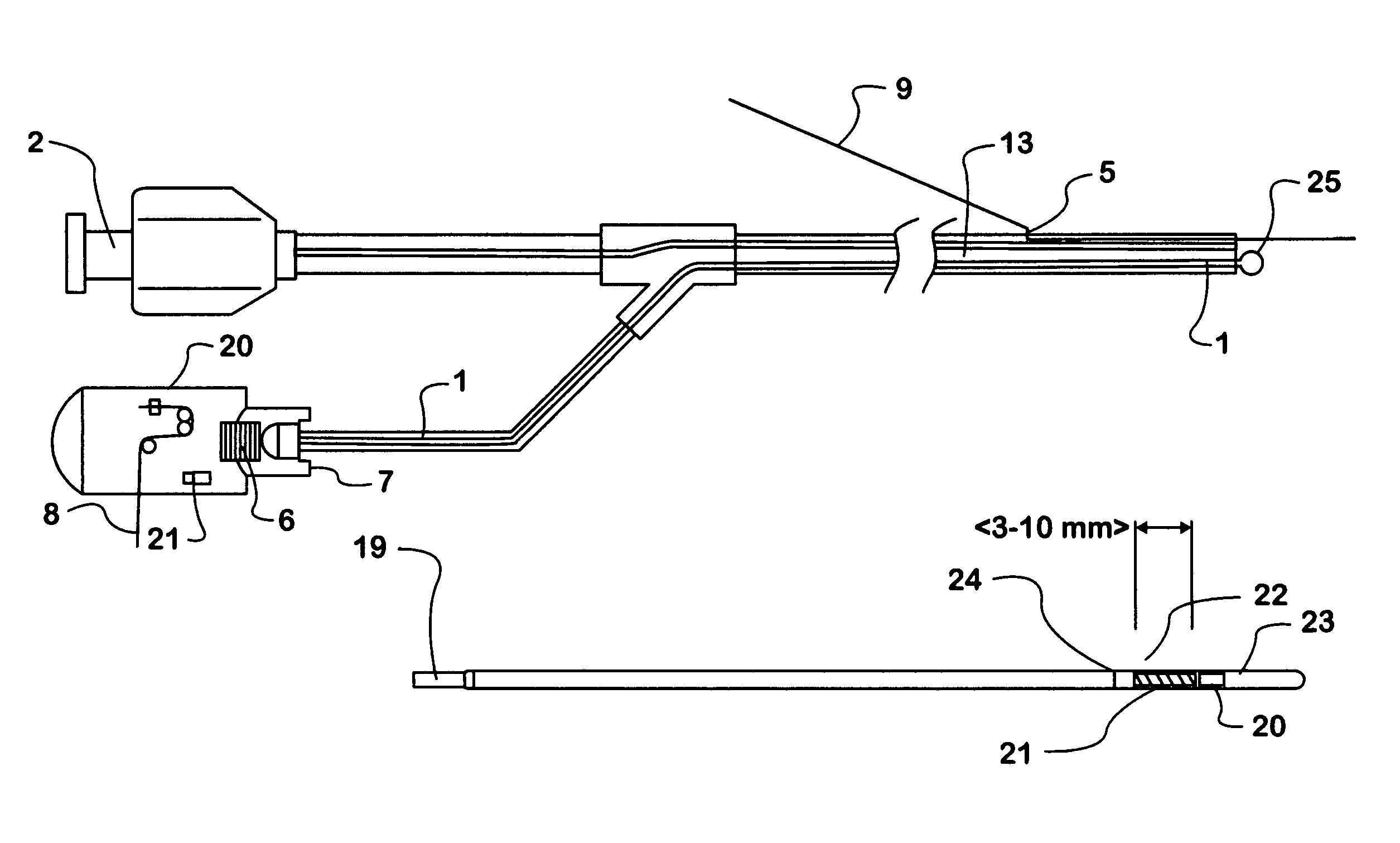
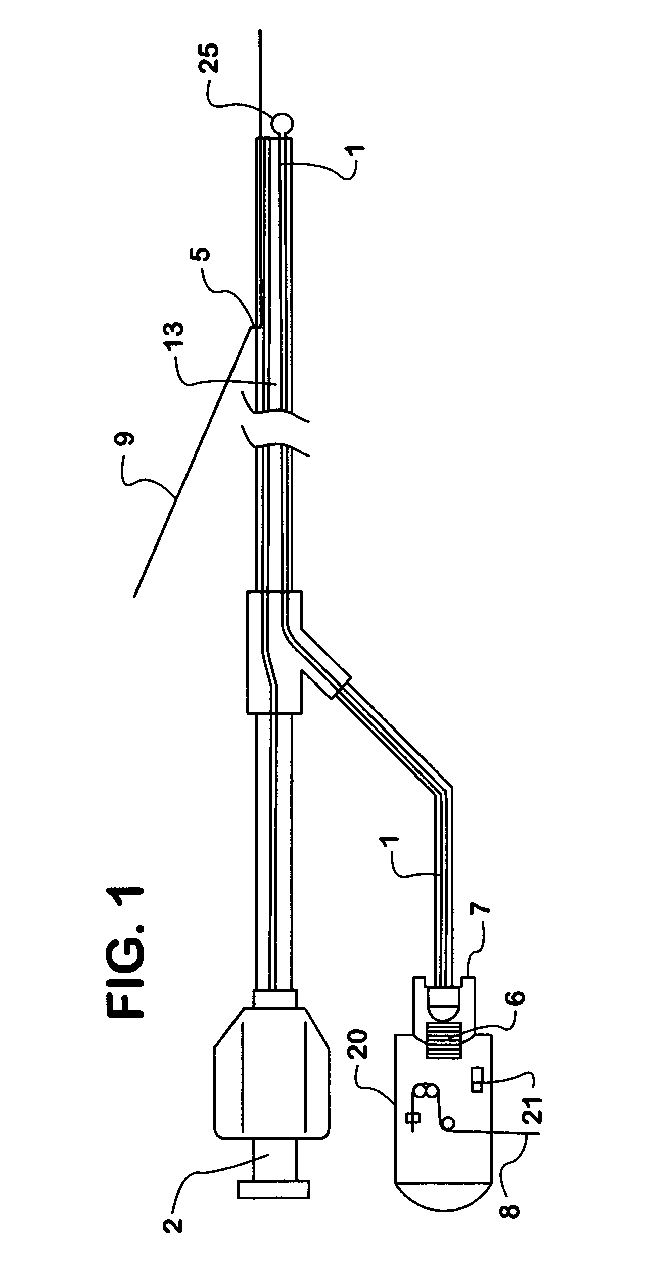
[0029]The preferred catheter is made from extruded plastic tube having a lumen to carry a fiber optic fiber or a bundle of optical fibers (1) in its entire length or part thereof. The fiber optic fiber is connected to a universal connector (UC) at the proximal end 7. An infrared source 6 is connected to the universal connector securely during irradiation. The infrared source is of a preferred wavelength between 700 and 2500 nanometer. The infrared source can be continuous or pulsed. Pulsing the infrared energy source will enable control of the power level delivered to the lesion. Pulsing can be accomplished by any one of different means of electrical circuitry.

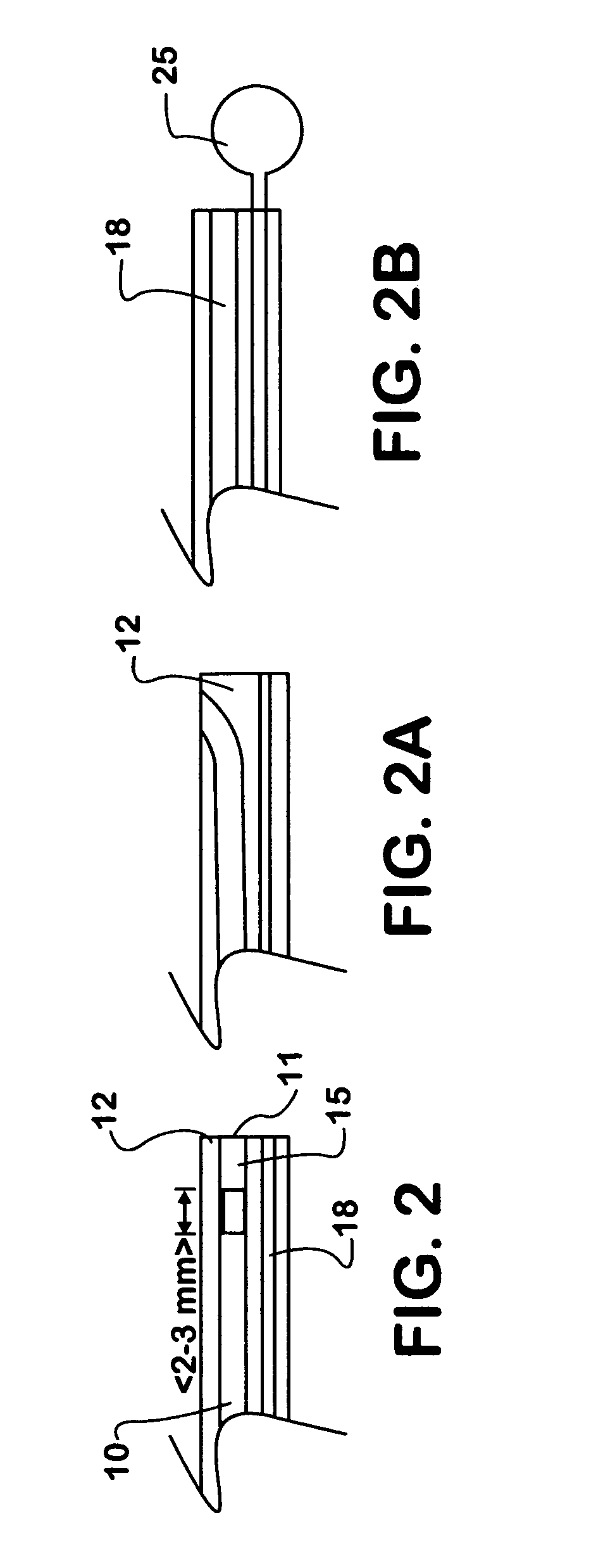
[0030]To advance the catheter to the desired lesion location, a guide wire (9) is used in the guide wire lumen 18. The same lumen can be used to flush the catheter if necessary. The catheter is threaded over the guidewire in the usual manner common to interventional procedures. The guide wire lumen has an opening 5 so that the...


PUM


Abstract

The method of vascular treatment for restenosis or vulnerable plaque after an invasive procedure, such as for example angioplasty, stenting with or without drug coating, or drug delivery, comprises: inserting a catheter or hollow guide wire to the treatment location; delivering light through the catheter in the wavelength range of about 700–2500 nm; and moving the light to treat the affected region.

Description

CROSS REFERENCE TO RELATED APPLICATIONS[0001]This application claims priority from Provisional Application No. 60 / 317,739, filed Sep. 6, 2001, of the same title.FIELD OF INVENTION[0002]The present invention relates to the method of treating tissue in a body cavity to minimize the scar tissue formation, after injury to the tissue by mechanical or by other intervention.BACKGROUND OF THE INVENTION[0003]When a catheter or other medical device is used in a body cavity, such as an artery, the mechanical rubbing of the catheter, or inflation of the balloon of a balloon angioplasty catheter, or the placement of a stent, can trigger the body to react to such mechanical injury. The body reacts by, among other processes, producing smooth muscle cell and fibroblast migration to the injury site. The body, depending on the location, may also produce endothelial cells and epithelial cells at injury site.[0004]In the case of balloon angioplasty, such reaction by the body will cause a build-up of sc...

Claims


Application Information

Patent Timeline
IPC IPC(8): A61B18/18A61B17/22A61B18/22A61B18/24
CPCA61B18/245A61B2017/22002A61B2018/2261
Inventor STONE, GREGG W.MOSES, JEFFREY W.LEON, MARTIN B.KIPSHIDZE, NICHOLAS N.SAHOTA, HARVINDERWIJAY, BANDULA
Owner STONE GREGG W
Why Eureka
Try Eureka