Patient specific implantation method for range of motion hip impingement

a patient-specific, hip-implanting technology, applied in the field of patient-specific hip-implanting implantation methods, can solve the problems of excessive wear and failure of components, permanent dislocation of the head, and excessive liner wear

Active Publication Date: 2017-05-11
HOWMEDICA OSTEONICS CORP
View PDF4 Cites 17 Cited by
  • Summary
  • Abstract
  • Description
  • Claims
  • Application Information

AI Technical Summary

Benefits of technology

[0029]The data for virtual representation of the hip stem and acetabular cup may be obtained from a computer aided design (CAD) system used for the fabrication of the hip stem and acetabular cup. This data may be stored in the memory of a computer being used to perform the virtual hip stem/cup motion. A safe zone is calculated when ca...

Problems solved by technology

Should the stem and cup not be positioned/aligned accurately, the neck of the stem may impinge on the lip of the insert resulting in a levering action that could allow the femoral head to cam out of the insert resulting in a permanent dislocation of the head.
The impingement can also lead to excessive component wear and possibly failure.
In addition, a malpositioned cup can result in excessive liner wear even without impingement.
A shell with a high abduction (inclination) angle can have joint forces concentrated near the cup liner rim, thereby increasing the wear rate due to concentrated forces.
Stem/cup impingement can serve as a fulcrum that could lever the femoral head out of the cup, which is called dislocation, a serious clinical issue.
However, this data, for the most part, is not currently available to the surgeon to take into consideration.
It has been found based on post-operative x-rays, however, that despite the alignment guide being parallel to the floor during insertion, of the acetabular cup, the resultant inclination or anteversion of the acetabulum in relation to the alignment guide is often different than expected and, thus, the acetabular cup has been installed at a less than ideal position.
Some of the drawbacks of this type of instru...

Method used


Image

  • Patient specific implantation method for range of motion hip impingement
  • Patient specific implantation method for range of motion hip impingement
  • Patient specific implantation method for range of motion hip impingement

Examples


Embodiment Construction

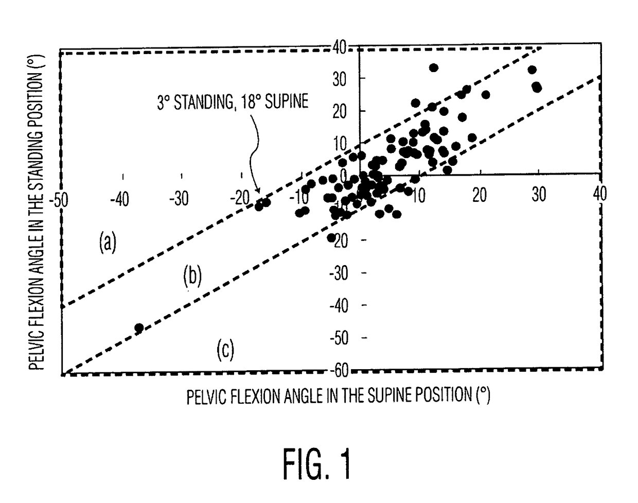
[0047]FIG. 1 is a plot of pelvic flexion angles in the supine position versus those in the standing position. Patients were divided into three groups. There was (a) greater than 10° flexion of the pelvis from the supine to the standing position in two of the 101 patients, (b) 10° or less pelvic flexion angle in 91 of the 101 patients (shown for example as 3° standing and 18° supine), and (c) greater than 10° extension of the pelvis in eight of the 101 patients.

[0048]In current orthopaedic surgery, it is assumed that Pelvic Tilt changes from standing to supine are negligible. That when a patient lays down supine on an operating room (OR) table or to have an anterior-posterior (AP) x-ray taken, or to have a CT taken, that any change in the pelvis flexing forward or backward is negligible.

[0049]In reviewing published data on pelvic tilt, these papers show a “general” correlation between standing and supine pelvic flexion (tilt). A point on a 45° angle would show that the pelvic tilt of...


PUM


Abstract

A method for avoiding impingement between an implanted prosthetic hip stem and acetabular cup uses at least one digital x-ray of a standing patient preferably including a lateral x-ray to determine a pelvic tilt angle of the patient. A hip stem is virtually implanted at an initial stem version angle into a virtual femur constructed from the digital x-ray. Data of at least one hip joint motion is obtained from at least one individual. A range of inclination and anteversion angles is calculated for a virtually implanted acetabular cup that avoids impingement with the virtually implanted hip stem. The calculated range of inclination or anteversion angles is based at least in part on the pelvic tilt angle of the patient, the initial hip stem version angle and the obtained joint motion data.

Description

CROSS-REFERENCE TO RELATED APPLICATIONS[0001]This application claims the benefit of the filing date of U.S. Provisional Patent Application No. 62 / 251,441 filed Nov. 5, 2015, the disclosure of which is hereby incorporated herein by reference.BACKGROUND OF THE INVENTION[0002]This invention relates to a method for avoiding impingement between an acetabular cup and a femoral component; a femoral component and bone; or bone and bone.[0003]Hip surgery requires the implantation of a femoral stem and an acetabular cup. The femoral stem has a spherical head that attaches to the neck of the stem and is free to articulate within a bearing insert that is fitted into the shell of an acetabular cup. Should the stem and cup not be positioned / aligned accurately, the neck of the stem may impinge on the lip of the insert resulting in a levering action that could allow the femoral head to cam out of the insert resulting in a permanent dislocation of the head. The impingement can also lead to excessive...

Claims


Application Information

Patent Timeline
IPC IPC(8): A61B34/10A61F2/46A61B5/11A61F2/36A61B6/00A61F2/34
CPCA61B34/10A61B6/505A61F2/34A61B5/1121A61F2002/30952A61F2/468A61B2034/104A61F2002/4633A61F2002/4668A61F2/3662
Inventor MCCARTHY, THOMAS FRANCISALIPIT, VINCENT
Owner HOWMEDICA OSTEONICS CORP
Why Eureka
Try Eureka