
Load sensor-equipped bearing device

a technology of load sensor and bearing device, which is applied in the direction of force sensor, force/torque/work measurement apparatus, instruments, etc., can solve the problems of deteriorating motion performance of the automobile, affecting the safety of the driver, so as to prevent the overloading of the vehicle

Inactive Publication Date: 2017-05-11
NSK LTD
View PDF4 Cites 10 Cited by
  • Summary
  • Abstract
  • Description
  • Claims
  • Application Information

AI Technical Summary

Benefits of technology

The present disclosure aims to provide a cost-effective load sensor-equipped bearing device that can detect the load in the compression direction acting on a bearing that rotatably supports axial load to prevent overloading of a vehicle.

Problems solved by technology

In an automobile, particularly a commercial vehicle such as a truck, a van and the like for transporting a variety of goods, an illegal overloaded vehicle that travels on a road with exceeding legal load capacity becomes a social issue.
(1) The overloading may deteriorate motion performance of the automobile and damage constitutional components.
Therefore, for example, an axle (hub) is broken, a tire is damaged (burst), a braking distance increases, a brake is overheated and poorly operates, and a vehicle is likely to overturn.
That is, an accident may be caused.
(2) Since the overloading causes severe damage to the road, the maintenance cost of the road increases.
There are many causes that it is difficult to prevent the overloading.
One of them is that a driver, a passenger and the like cannot easily recognize the loaded weight.
However, the installation of the platform scale requires a large facility and a wide installation space, so that the installation cost increases.
Therefore, the number of platform scales to be installed is limited, so that it is difficult to measure many vehicles.
However, according to the load measurement device of the related art like Patent Document 1, since the configuration is complicated and it is necessary to provide the circuit board, the amplifier and the like, the cost increases.
Also, since the load measurement device is disposed at a place at which it is likely to be shocked, a problem may be caused to the circuit board, the amplifier and the like.

Method used


Image

  • Load sensor-equipped bearing device
  • Load sensor-equipped bearing device
  • Load sensor-equipped bearing device

Examples


Embodiment Construction

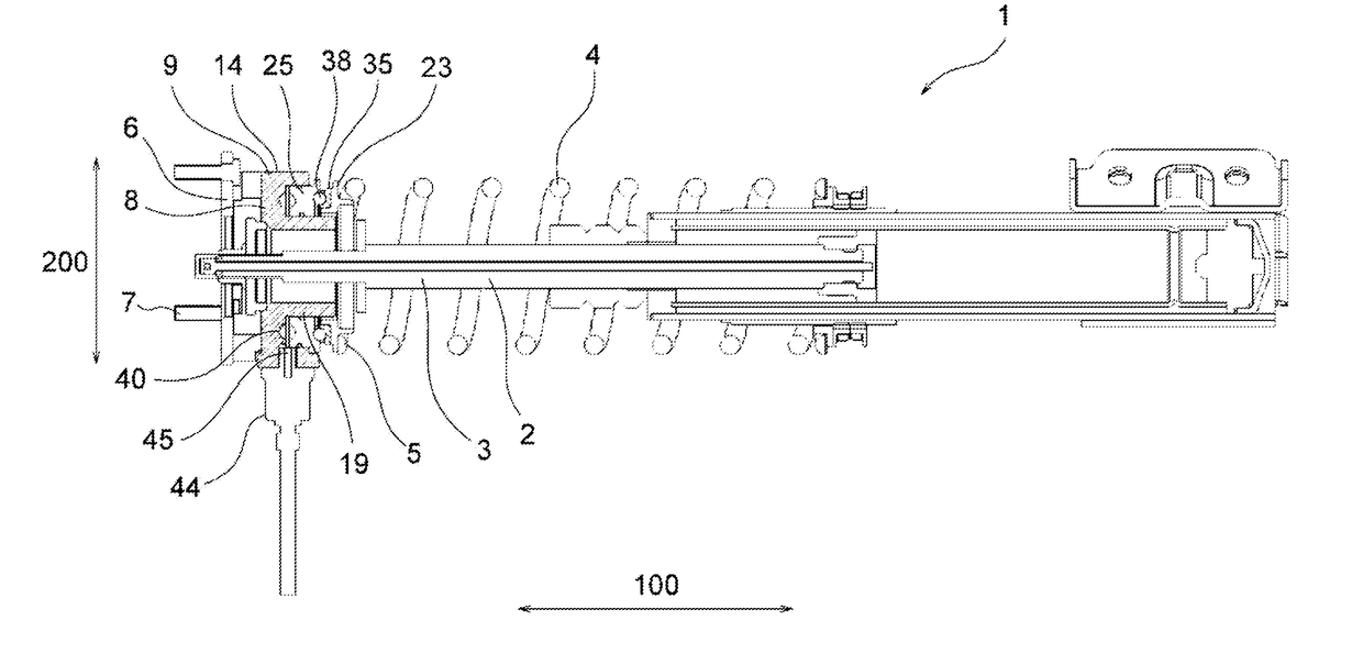
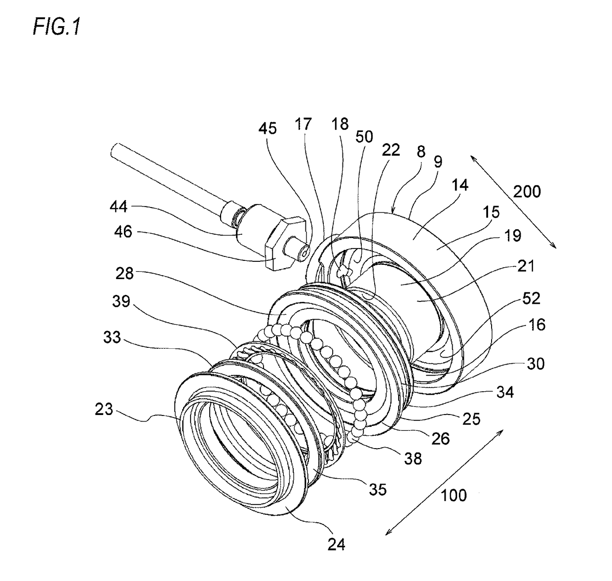
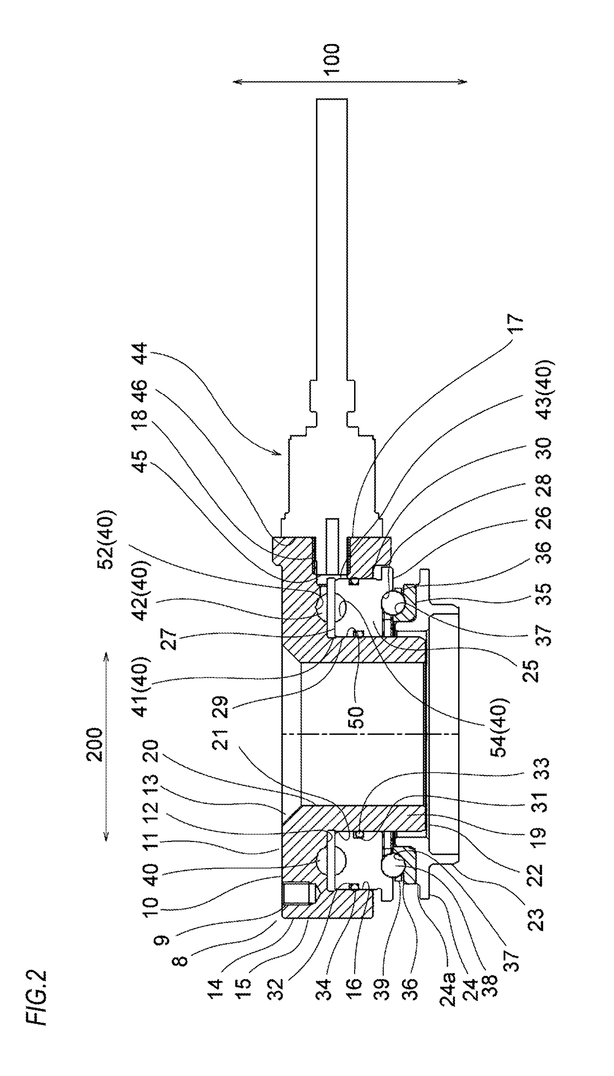
[0032]Hereinafter, an embodiment of a load sensor-equipped bearing device (which may also be referred to as a bearing device) of the present disclosure will be described with reference to the drawings. This embodiment relates to an example where the bearing device is used for a suspension of an automobile. In the meantime, the embodiment is just an embodiment of the present disclosure, is not construed to limit the present disclosure and can be design-changed within the scope of the present disclosure.

[0033]FIGS. 1 to 4 depict the bearing device of the embodiment. FIGS. 5 and 6 depict an example where the bearing device of the embodiment is incorporated to a suspension 1 of an automobile (for example, a small commercial vehicle such as a truck, a van or the like). Although not shown, an upper side of the suspension 1 is fixed to a main body frame (cross member) of the automobile, and a lower side is fixed to an axle via a lower arm pivotally mounted to a frame. In the meantime, the ...


PUM


Abstract

A bearing raceway ring (25) disposed near a mounting section (9) is disposed on the outer periphery of a circular cylinder section (19). A fluid-sealed chamber (40) in which a measurement liquid is hermetically enclosed is provided between a first member (8) and the bearing raceway ring (25) which is disposed near the mounting section (9). Pressure acting on the fluid to be measured changes as the bearing raceway ring (25) moves in the cylinder-axis direction, the bearing raceway ring (25) being disposed near the mounting section (9). The fluid-sealed chamber (40) is provided with a pressure sensor (44) capable of detecting a change in the pressure of the fluid to be measured.

Description

TECHNICAL FIELD[0001]The present disclosure relates to a technology of measuring load in a direction of pressing a bearing, and more particularly to, a load sensor-equipped bearing device to be incorporated to a suspension of an automobile and configured to measure tire load.RELATED ART[0002]In an automobile, particularly a commercial vehicle such as a truck, a van and the like for transporting a variety of goods, an illegal overloaded vehicle that travels on a road with exceeding legal load capacity becomes a social issue. The overloading reason is that it is possible to save the transportation cost when carrying many goods at one time.[0003]However, the overloading should be avoided because it can cause a variety of problems, as follows.[0004](1) The overloading may deteriorate motion performance of the automobile and damage constitutional components. Therefore, for example, an axle (hub) is broken, a tire is damaged (burst), a braking distance increases, a brake is overheated and...

Claims


Application Information

Patent Timeline
IPC IPC(8): F16C19/52G01L5/00G01L1/02F16C19/12
CPCF16C19/522F16C19/12F16C2233/00G01L1/02F16C2326/05G01L5/0009B60G15/068B60G17/019B60G2204/11B60G2204/418B60G2400/51B60G2400/60B60T7/042B60T7/12B60T7/18B60T8/1875B60T10/02B60T8/18F16C19/10F16C41/00F16D57/04G01G19/10
Inventor MATSUDA, YASUYUKIUEDA, TOHRUHIKIDA, MASAFUMI
Owner NSK LTD
Learn More