Laser device

a laser device and laser technology, applied in the field of laser devices, can solve the problems of measurement errors, difficult to remove stray light interference, etc., and achieve the effect of reducing the parallax of light transmitters and light receivers, and reducing stray light interferen

Active Publication Date: 2017-05-11
FUNAI ELECTRIC CO LTD
View PDF6 Cites 6 Cited by
  • Summary
  • Abstract
  • Description
  • Claims
  • Application Information

AI Technical Summary

Benefits of technology

[0031]The laser device according to one or more embodiments of the present invention may reduce the parallax of the light transmitter and the light receiver, and decrease stray light interference.

Problems solved by technology

Laser devices that employ a coaxial optical system do not have measurement errors due to a parallax of the light transmitter and the light receiver because the optical axis of the measuring light and the optical axis of the returning light are aligned, however there is a disadvantage in that it is difficult to remove stray light interference wherein stray light generated by the measuring light being diffusely reflected in the housing wraps around the light receiver.
This stray light interference is a possible cause for measurement errors.

Method used


Image

  • Laser device
  • Laser device
  • Laser device

Examples


first embodiment

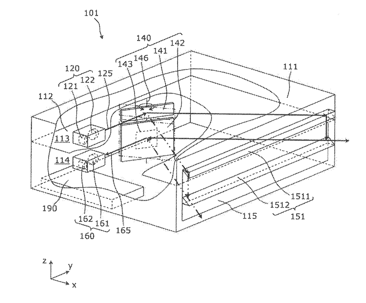
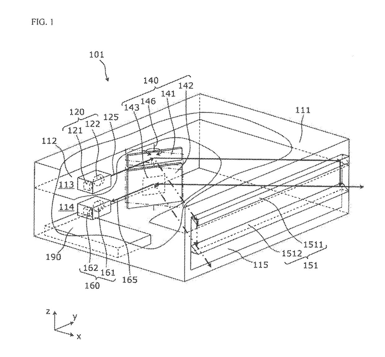
[0050]The laser device according to the present invention is a laser device for measuring a distance to a target object, by moving a measurement light that is emitted from a light transmitter by a light transmitting mirror (first reflector), scanning the range area, and receiving a returning light of the measuring light from the target object by a light receiver via a light receiving mirror (second reflector). The laser device may be called a measuring apparatus. The laser device separates the optical path of the measuring light and the optical path of the returning light that is reflected by the oscillating mirror, decreasing stray light interference, while an optical axis shift part (guide part) is provided for shifting the optical axis of the measuring light close to the light receiver in the latter stage of the oscillating mirror.

[0051]First, the laser device configuration according to the first embodiment of the present invention will be described.

[0052]FIG. 1 is a cutout persp...

second embodiment

[0100]the present invention will be described in detail with reference to drawings.

[0101]FIG. 9 is a cutout perspective view drawing illustrating an example configuration of a laser device 103 according to the second embodiment of the present invention.

[0102]As illustrated in FIG. 9, with regard to the laser device 103, the point where a housing window 116 is provided on a cylindrical shape as the center of the oscillating shaft 146 is different in comparison with the laser device 101 of FIG. 1. The shape of a first reflection part 1531 and a second reflection part 1532 configured of an optical axis shift part 153 has been changed, consequent upon changes to the shape of the housing window 116. The laser device 103 is the same as the laser device 101, with the exception of the point where the shape of the housing window 116 and the optical axis shift part 153 has been changed.

[0103]Configurations of the optical axis shift part 153 will be described in detail.

[0104]FIG. 10 is a persp...

third embodiment

[0124]the present invention will be described specifically with reference to drawings.

[0125]FIG. 14 is a side view drawing illustrating an example of the optical path of the measuring light and returning light of a laser device 105 according to the third embodiment of the present invention.

[0126]As illustrated in FIG. 14, an optical axis shift part 155 of the laser device 105 is different in comparison with the laser device 101 of FIG. 7. The components are the same as the laser device 101, with the exception of the optical axis shift part 155 in the laser device 105.

[0127]The optical axis shift part 155 of the laser device 105 can be configured to change the height of the emitting position of the measuring light 125. The configuration of the optical axis shift part 155 is not particularly limited, however, as an example, both ends of a second reflection part 1552 are held by a moveable holding member (not illustrated) provided on the housing 111, and the second reflection part 1552...


PUM


Abstract

A laser device includes a transmitter that emits a light, a first reflector that pivotally reflects the light by a shaft, a light receiver provided apart from the transmitter in a first direction parallel to the shaft, a guide part that receives the light from the first reflector and changes a direction of the light in the first direction, and a second reflector that reflects a returning light from an object and pivots in sync with the first reflector.

Description

BACKGROUND[0001]Technical Field[0002]The present invention generally relates to a laser device (measuring apparatus) for measuring distance to a target object by using light.[0003]Related Art[0004]Conventional measuring apparatuses measure distance to a target object by using a moveable mirror to deflect and emit a measuring light in a plurality of directions, thereby receiving the returning light of the measuring light as reflected by the target object via the moveable mirror.[0005]As an example, a measuring apparatus for what is called a coaxial optical system is known, whereby the measuring light and the returning light enters and exits along the same optical axis by using an optical element such as a prism or mirror and the like, aligning the central axis of a light transmitter and the central axis of a light receiver (for example, refer to patent documents 1, 2).[0006]Patent Literature 1: Japanese Patent Application Publication No. 2011-59111[0007]Patent Literature 2: Japanese ...

Claims


Application Information

Patent Timeline
Patent Type & Authority Applications(United States)
IPC IPC(8): G01S7/481G01S17/08
CPCG01S7/4812G01S7/4817G01S17/08G01S7/481G01S7/4813
Inventor MASUDA, YUICHIRO
Owner FUNAI ELECTRIC CO LTD
Why Eureka
Try Eureka