Surveying System

a technology of a surveillance system and a camera, applied in the field of surveillance systems, can solve the problems of heavy burden on the operator and high time required for sighting, and achieve the effect of easy trilatation and heavy burden of operation

Active Publication Date: 2017-05-11
KK TOPCON
View PDF0 Cites 21 Cited by
  • Summary
  • Abstract
  • Description
  • Claims
  • Application Information

AI Technical Summary

Benefits of technology

[0006]It is an object of the present invention to provide a surveying system, by which it is possible to omit an angle measurement, which a burden of an operation is heavy, and to perform a trilateration easily.

Problems solved by technology

Further, since in the total station, it is necessary to sight a plurality of the measuring points each time, much time is required for sighting, and a burden on the operator is heavy.

Method used


Image

  • Surveying System
  • Surveying System
  • Surveying System

Examples


first embodiment

[0141]Next, referring to FIG. 10, a description will be given on a first embodiment to perform a trilateration by using the surveying instrument 1.

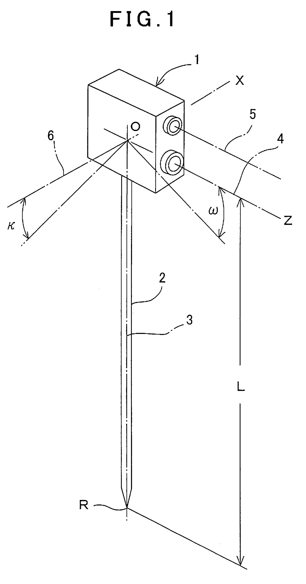
[0142]The surveying instrument 1 is installed in such a manner that a lower end of the monopod 2 is positioned at a first installation reference point R1 (a first position), which is a known point (the coordinates are already known).

[0143]A first image is obtained with respect to the object to be measured by the image pickup unit 27, and a measuring point 87 is selected from the image. Here, a selection of the measuring point 87 may be confirmed visually in the image or may be selected by an image processing such as a feature extraction (an edge extraction), or the like.

[0144]The distance measuring optical axis 4 is directed toward the measuring point 87, and a slope distance to the measuring point 87 is determined. It is to be noted that the distance measuring optical axis 4 and the image pickup optical axis 5 are regarded to be in a par...

second embodiment

[0154]Further, referring to FIG. 11, a description will be given on the trilateration.

[0155]As shown in FIG. 11, a surveying instrument 1 is installed in such a manner that a lower end of a monopod 2 is positioned at the installation reference point R, which is a known point (the coordinates are already known).

[0156]The surveying instrument 1 is tilted approximately in parallel and in one direction with respect to an object to be measured 81, a tilted state is regarded as a first position 86, and an image 85 (not shown) of the object to be measured 81 is acquired at the first position 86. The image 85 is displayed on a display unit 11. While observing the image 85, directions of a distance measuring optical axis 4 and an image pickup optical axis 5 are set so that a measuring position and a measuring area as planned are included in the image 85. After setting, one or more measuring points 87 are selected in the image 85. It is to be noted that the measuring point 87 is a point which...

third embodiment

[0190]Further, a description will be given on the trilateration by referring to FIG. 14.

[0191]A surveying instrument 1 is installed at a first installation position (a known installation reference point R) 88 via a monopod 2. A mechanical reference point O at this time is regarded as a first position 86. From the first position 86, a first image is acquired with respect to an object to be measured, and a measuring point 87 is selected in the image. A distance measurement is performed by a distance measuring unit 23 with respect to the measuring point 87 as selected, and a tilting of the surveying instrument 1 at the time of the distance measurement is detected by the attitude detecting unit 26. Based on this tilt angle and a distance L of the monopod 2, a positional relation between the installation reference point R and the first position 86 is determined. Further, the first position 86 is calculated by the arithmetic processing unit 24.

[0192]The surveying instrument 1 is installed...


PUM


Abstract

The invention provides a surveying system, which comprises a surveying instrument, wherein the surveying instrument comprises a measuring unit for performing a distance measurement by projecting a distance measuring light toward an object to be measured and by receiving a reflected distance measuring light from the object to be measured, an image pickup unit having an image pickup optical axis running in parallel to a projection optical axis of the distance measuring light and for picking up an image including the object to be measured, an attitude detecting unit provided integrally with the measuring unit and for detecting a tilt angle with respect to the horizontal of the measuring unit, a coordinates acquiring unit for detecting a position of the surveying instrument and an arithmetic processing unit, wherein a first image of the object to be measured is acquired by the image pickup unit from a first position where coordinates of the first position are acquired by the coordinates acquiring unit, a second image of the object to be measured is acquired by the image pickup unit from a second position where coordinates of the second position are acquired by the coordinates acquiring unit, wherein the measuring unit directs a distance measuring optical axis toward common measuring points as specified in the first image and the second image respectively, projects the distance measuring light, and carries out a first distance measurement from the first position and a second distance measurement from the second position, and wherein the arithmetic processing unit calculates horizontal distances from the first position and the second position respectively based on the tilt angles detected by the attitude detecting unit at the first position and the second position, on the first distance measurement and on the second distance measurement, and further the arithmetic processing unit is configured to calculate a base line length based on coordinates of the first position and on coordinates of the second position and to carry out a trilateration with respect to the measuring point based on the horizontal distance and on the base line length.

Description

BACKGROUND OF THE INVENTION[0001]The present invention relates to a surveying system for performing a trilateration in a simple and easy manner.[0002]In general, a surveying expresses a plurality of measuring points, which are objects on a ground surface, in relation to a horizontal distance and a height. As a surveying instrument to be used for the surveying, a total station is known, for instance.[0003]On a plurality of the measuring points, a distance (a slope distance), a vertical angle, and a horizontal angle are measured by the total station respectively, and the relations between the measuring points are obtained respectively.[0004]Since in the total station, it is necessary to measure an angle with high accuracy, the total station must be installed via a tripod at an installation point (a reference point), and further must be leveled horizontally with high accuracy. For this reason, a time for installing is required, and further, a high skill is required.[0005]Further, since...

Claims


Application Information

Patent Timeline
Patent Type & Authority Applications(United States)
IPC IPC(8): G01S17/48G01S7/481G01S17/89
CPCG01S17/48G01S7/4814G01S17/89G01C15/002G01S7/4812G01S7/4817
Inventor OHTOMO, FUMIOKUMAGAI, KAORUOTANI, HITOSHIANAI, TETSUJI
Owner KK TOPCON
Why Eureka
Try Eureka