Electric equipment system

a technology of electrical equipment and equipment, applied in the direction of electric programme control, program control, instruments, etc., can solve the problems of difficult modification of circuits, limited input/output functions, and inflexibility, and achieve the effect of complex input/output requirements in production lines

Active Publication Date: 2017-05-11
PANASONIC INTELLECTUAL PROPERTY MANAGEMENT CO LTD
View PDF7 Cites 0 Cited by
  • Summary
  • Abstract
  • Description
  • Claims
  • Application Information

AI Technical Summary

Benefits of technology

[0011]The present invention provides an electric equipment system that does not require that a new device for external input / output is introduced whenever a production line is newly constructed or modified, and can establish complex input / output requirements in a production line.
[0017]Thus, this configuration does not require that a new device for external input / output is introduced whenever a production line is newly constructed or modified, and can establish complex input / output requirements in a production line.

Problems solved by technology

The input / output function is restricted and has no flexibility, and addition or modification of a circuit is required in order to alter the function of the welding apparatus.
Each circuit is designed dedicatedly, so that the circuit is difficult to be modified.

Method used


Image

  • Electric equipment system
  • Electric equipment system
  • Electric equipment system

Examples


first exemplary embodiment

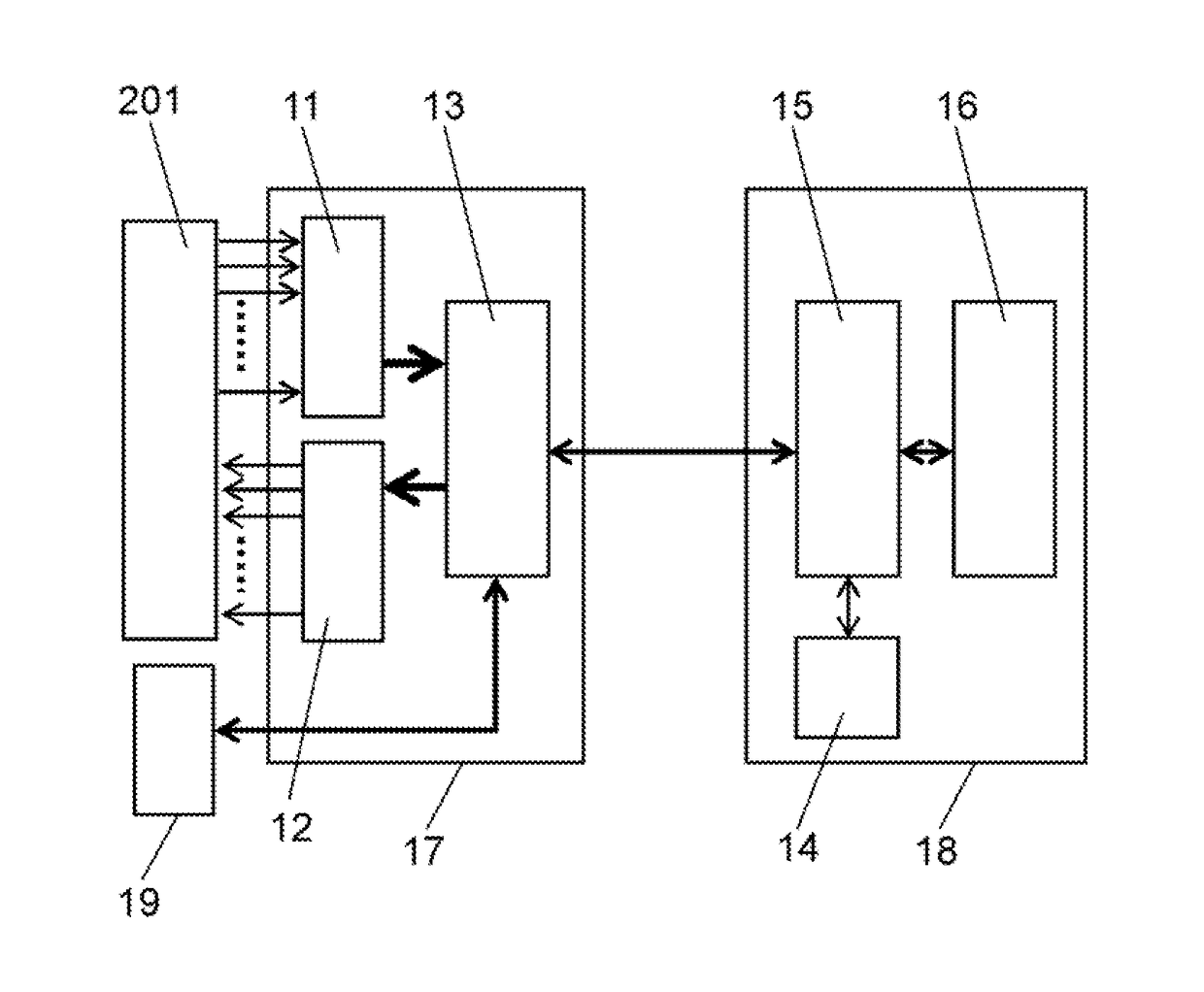
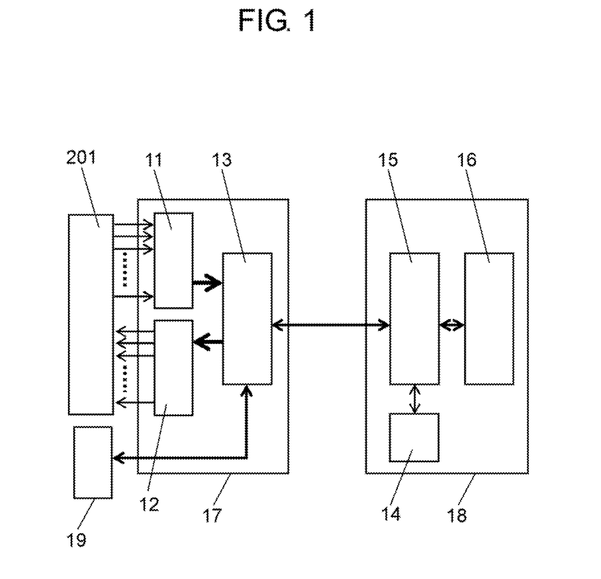
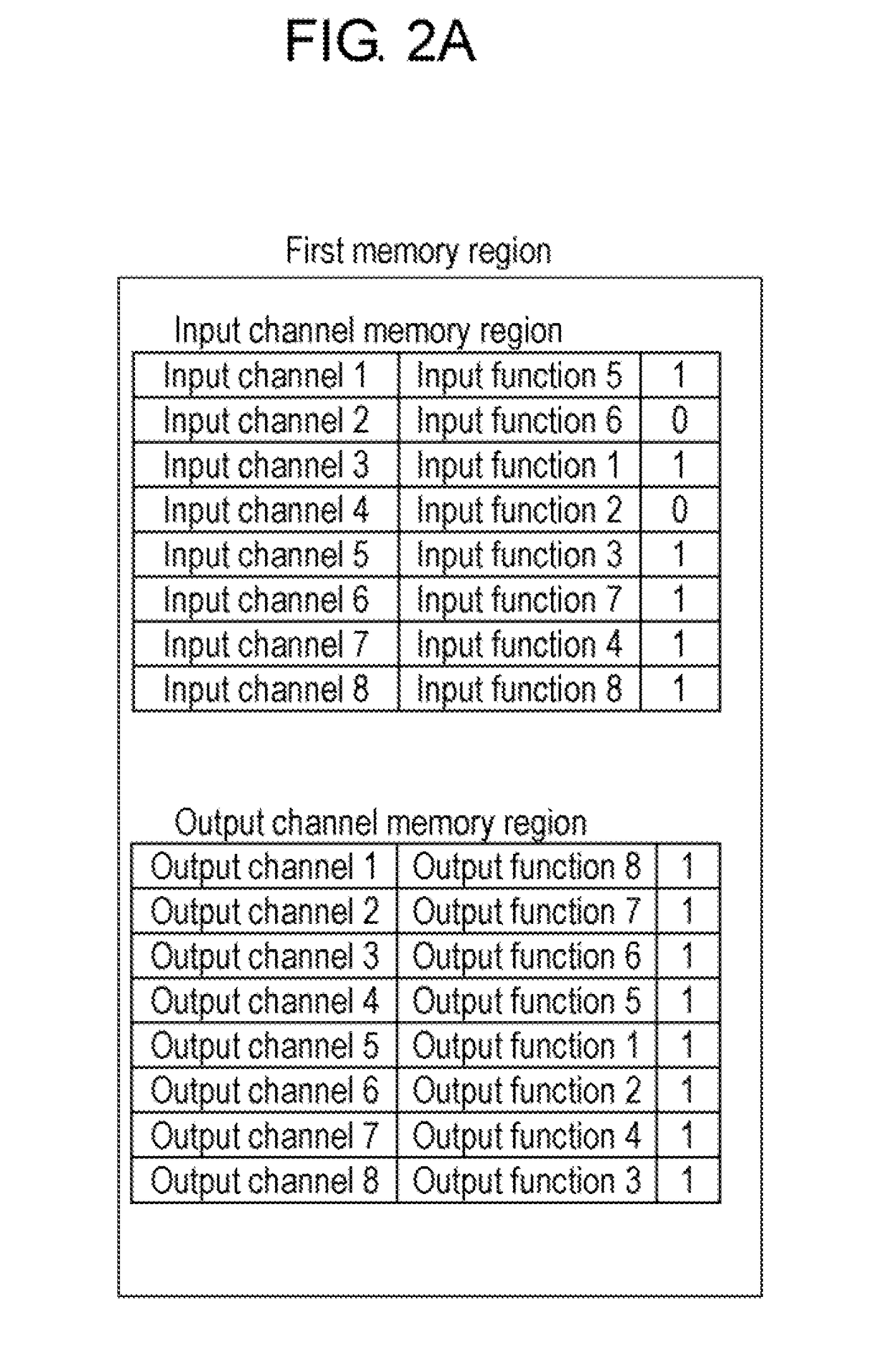
[0036]An electric equipment system of a first exemplary embodiment is described with reference to FIG. 1 through FIG. 3. As an example of the electric equipment system of a first exemplary embodiment, a welding apparatus is described. FIG. 1 is a schematic block diagram of an essential part of a welding system including an input / output device and welding apparatus in accordance with the first exemplary embodiment of the present invention. Each of FIG. 2A, FIG. 2B, FIG. 2C, and FIG. 2D is a diagram showing a memory region or a data format of storing section in accordance with the first exemplary embodiment of the present invention. FIG. 3 is a diagram showing an example of an operation screen of a personal computer (hereinafter referred to as “PC”) for assigning the input and output in accordance with the first exemplary embodiment of the present invention.

[0037]As shown in FIG. 1, welding apparatus 18 as electric equipment is communicably connected to input / output device 17. Input / o...

second exemplary embodiment

[0056]A second exemplary embodiment of the present invention is described with reference to FIG. 5, FIG. 6A, FIG. 6B, and FIG. 6C. FIG. 5 is a schematic block diagram of an essential part of a welding system including an input / output device and welding apparatus in accordance with a second exemplary embodiment of the present invention. Each of FIG. 6A, FIG. 6B, and FIG. 6C is a diagram showing an example of the outline and operation screen of a controller in accordance with the second exemplary embodiment.

[0057]The second exemplary embodiment differs from the first exemplary embodiment in the configuration of welding apparatus 18. Welding apparatus of the second exemplary embodiment does not include welding-apparatus-side input / output control section 15 of FIG. 1, but includes welding-apparatus-side input / output control section 21 of controller connection type as shown in FIG. 5. Controller 20 assigns the input and output.

[0058]As shown in FIG. 5, controller 20 includes several swit...

third exemplary embodiment

[0083]A third exemplary embodiment of the present invention is described with reference to FIG. 8 through FIG. 11. FIG. 8 is a schematic block diagram of an essential part of a welding system including an input / output device and welding apparatus in accordance with the third exemplary embodiment of the present invention. FIG. 9 is a diagram showing an example of a logical expression memory in accordance with the third exemplary embodiment of the present invention. FIG. 10 is a diagram showing an example of an operation screen of a PC for assigning the input and output and inputting a logical expression in accordance with the third exemplary embodiment of the present invention. FIG. 11 is a diagram showing an example during execution of the logical expression in accordance with the third exemplary embodiment of the present invention.

[0084]The electric equipment system of the third exemplary embodiment differs from that of the first exemplary embodiment in that the electric equipment ...


PUM

PropertyMeasurementUnit
AC voltageaaaaaaaaaa
frequencyaaaaaaaaaa
flexibilityaaaaaaaaaa

Abstract

An input / output device inputting and outputting information to an external device includes a control section for communicating with an external controller. Electric equipment for communicating with the input / output device includes an input / output assignment storing section for storing which port of an input circuit an input from the external device is assigned to, and which port of an output circuit an output is assigned to. The electric equipment also includes an electric-equipment-side input / output control section for operating a function of the electric equipment based on information from the control section, or transmitting, to the control section, the information indicating which port of the output circuit an output of the electric equipment is output to. The electric equipment, using the external controller, stores the information related to the assignment in the input / output assignment storing section, or alters the information related to the assignment stored in the input / output assignment storing section.

Description

1. TECHNICAL FIELD[0001]The present invention relates to an electric equipment system including an input / output device for inputting / outputting information and electric equipment such as a welding apparatus used in a connecting state to the input / output device.2. BACKGROUND ART[0002]In a welding apparatus as an example of conventional electric equipment, a dedicated input / output circuit performs the input from the outside of the welding apparatus or the output to the outside (for example, Unexamined Japanese Patent Publication No. H04-17977). The input / output function is restricted and has no flexibility, and addition or modification of a circuit is required in order to alter the function of the welding apparatus.[0003]FIG. 12 shows a configuration example of conventional welding apparatuses. FIG. 12 describes only a section for receiving information from the outside, and omits a configuration such as a welding output section that is required for arc welding.[0004]Hereinafter, the w...

Claims


Application Information

Patent Timeline
Patent Type & Authority Applications(United States)
IPC IPC(8): G05B19/05B23K9/10
CPCG05B19/054G05B2219/45135G05B2219/1208B23K9/1087B23K9/10G06F3/002
Inventor IHARA, HIDEKIMATSUMOTO, KAZUNORITANAKA, YOSHIAKITAKEMURA, KOUSUKE
Owner PANASONIC INTELLECTUAL PROPERTY MANAGEMENT CO LTD
Why Eureka
Try Eureka