
Chuck driving gear pair structure for laser cutting equipment

A laser cutting and driving gear technology, which is applied in laser welding equipment, welding equipment, metal processing equipment, etc., can solve the problems that affect the processing accuracy of laser cutting equipment, the large size and weight of the driving gear pair, and reduce the rotation accuracy of the chuck. Achieve the effects of shortening production time, improving machining accuracy, and facilitating positioning operations

Pending Publication Date: 2021-10-26
常州凯莱德传动机械有限公司
View PDF0 Cites 0 Cited by
  • Summary
  • Abstract
  • Description
  • Claims
  • Application Information

AI Technical Summary

Problems solved by technology

[0004] However, the traditional drive gear pair is not only connected in a fixed way, but the gear style is mostly simple structure, resulting in excessive size and weight of the drive gear pair, which not only increases the production cost, but also reduces the rotation accuracy of the chuck, affecting Improve the processing accuracy of laser cutting equipment

Method used


Image

  • Chuck driving gear pair structure for laser cutting equipment
  • Chuck driving gear pair structure for laser cutting equipment
  • Chuck driving gear pair structure for laser cutting equipment

Examples


Embodiment Construction

[0027] The following will clearly and completely describe the technical solutions in the embodiments of the present invention with reference to the accompanying drawings in the embodiments of the present invention. Obviously, the described embodiments are only some, not all, embodiments of the present invention. Based on the embodiments of the present invention, all other embodiments obtained by persons of ordinary skill in the art without making creative efforts belong to the protection scope of the present invention.

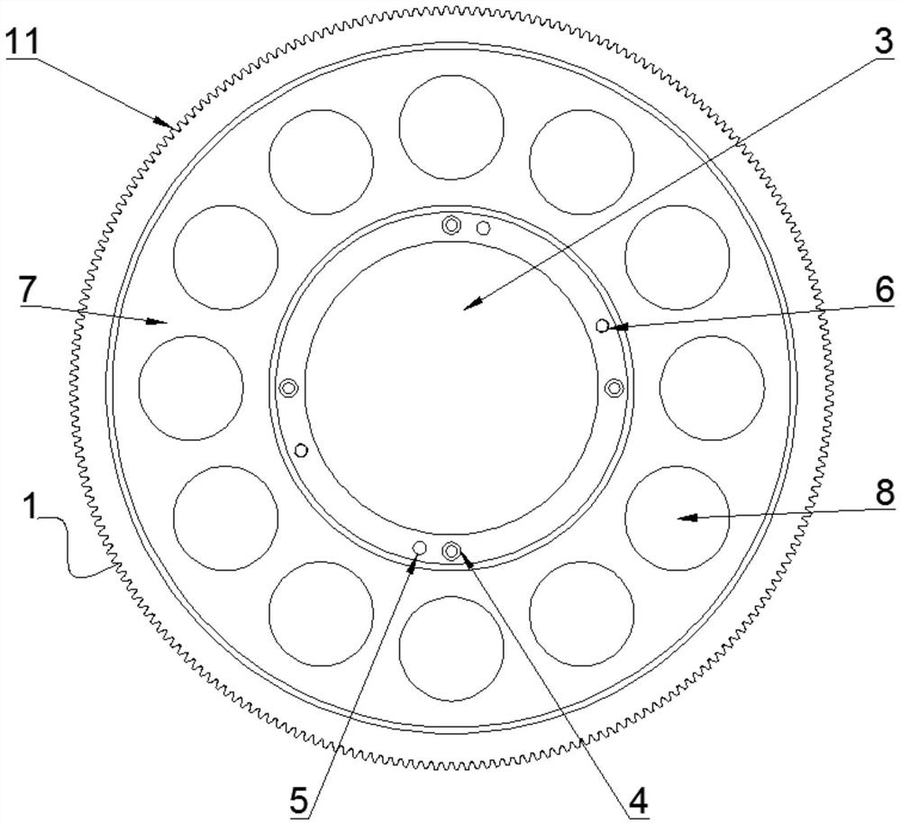
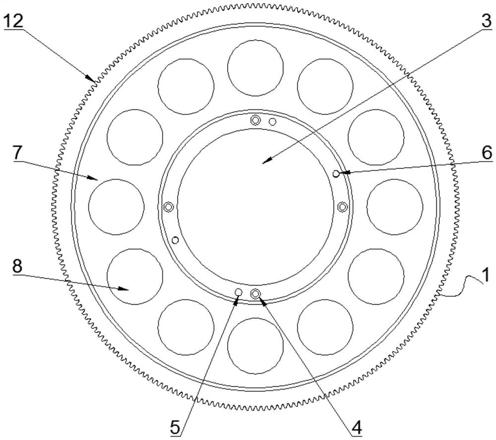
[0028] see Figure 1-12, the present invention provides a technical solution: a chuck drive gear pair structure used in laser cutting equipment, including a driven gear set 1, a driving gear set 2, a shaft hole 3, a fixing bolt hole 4, a positioning pin hole 5, a top Screw hole 6, hub groove 7, lightening hole 8 and keyway 9, driven gear set 1 is made up of first driven gear 11 and second driven gear 12, first driven gear 11 and second driven gear 12 There ar...


PUM


Abstract

The invention discloses a chuck driving gear pair structure for laser cutting equipment. The chuck driving gear pair structure comprises a driven gear set, a driving gear set, a shaft hole, a fixing bolt hole, a positioning pin hole, a jacking screw hole, a hub groove, lightening holes and a key groove. According to the chuck driving gear pair structure, the positioning pin hole is arranged, so that the positioning operation during the installation by a worker is facilitated, the installation precision of the driven gear set is improved, the transmission loss between the driven gear set and a chuck rotating shaft is reduced, and resources are saved; the jacking screw hole is arranged, so that the jacking operation during the disassembly by the worker is facilitated, the production time is shortened, and the labor cost is reduced; the hub groove and the lightening holes are arranged, so that the weight of the driven gear set is reduced, the rotational inertia of a chuck is reduced, and the machining precision of the laser cutting equipment is improved; and the shaft hole, the fixing bolt hole and the key groove are formed in a combined manner, so that a driving gear pair can be connected with chucks and speed reducers of various type, the adaptability of the driving gear pair is improved, and the complex requirements in actual production are met.

Description

technical field [0001] The invention relates to the technical field of laser cutting equipment, in particular to a chuck driving gear pair structure used in laser cutting equipment. Background technique [0002] Laser cutting equipment mainly uses the heat energy generated by the laser beam emitted by the laser, and cooperates with the motion mechanical system to realize the cutting of the pipe. The cut pipe is controlled by an intelligent system, which can achieve high-quality and high-efficiency production purposes. [0003] The processing accuracy of laser cutting equipment is the first factor to judge the quality of the equipment, and the important part that affects the cutting accuracy is the chuck. Machining accuracy, the rotation accuracy of the chuck is mainly determined by the gear pair driving the chuck, so the structure of the driving gear pair directly affects the processing accuracy of the laser cutting equipment. [0004] However, the traditional drive gear pa...

Claims


Application Information

Patent Timeline
Patent Type & Authority Applications(China)
IPC IPC(8): B23K26/38B23K26/70B23K101/06
CPCB23K26/38B23K26/702B23K2101/06
Inventor 马建润
Owner 常州凯莱德传动机械有限公司
Learn More