Concealed flow regulator

Active Publication Date: 2017-05-18
XIAMEN SOLEX HIGH TECH IND CO LTD
View PDF6 Cites 2 Cited by
  • Summary
  • Abstract
  • Description
  • Claims
  • Application Information

AI Technical Summary

Benefits of technology

[0027]7. it has a deflecting annular wall, the water flowing clearance is disposed in the deflecting annular wall that water flows through the water flowing clearance and then directly flows to the deflecting annular wall, it can reduce the pressure loss of the water during flowing from the water flowing clearance to the diversion holes, so that it can obtain higher volume even in low water pressure and reduce the noise of the impacting of the water. The water stop ring is supported on the support seat and surrounds the central seat, when the water pressure works on the elasti

Problems solved by technology

The sealing portion is disposed at the upper end of the inner side of the hous

Method used


Image

  • Concealed flow regulator
  • Concealed flow regulator
  • Concealed flow regulator

Examples


Embodiment Construction

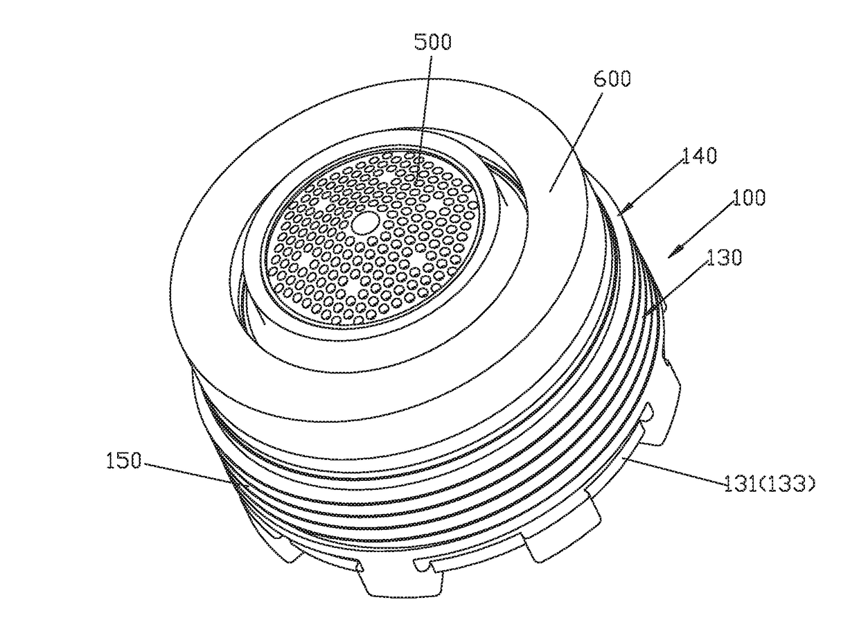
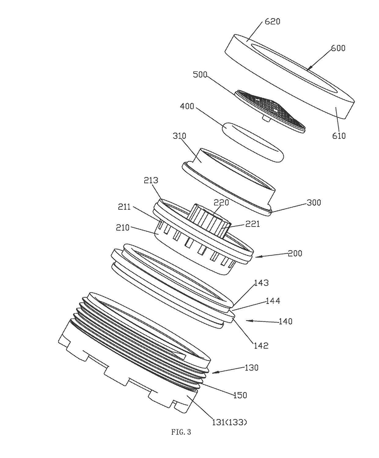
[0041]Please referring to FIGS. 1-11, the concealed flow regulator comprises a housing portion 100, a diversion device 200 assembled in the housing portion 100, an annular seat 300, an elastic water stop ring 400, a filter 500 and a sealing portion 600, the annular seat 300, the diversion device 200 are fixedly assembled to the housing portion 100.

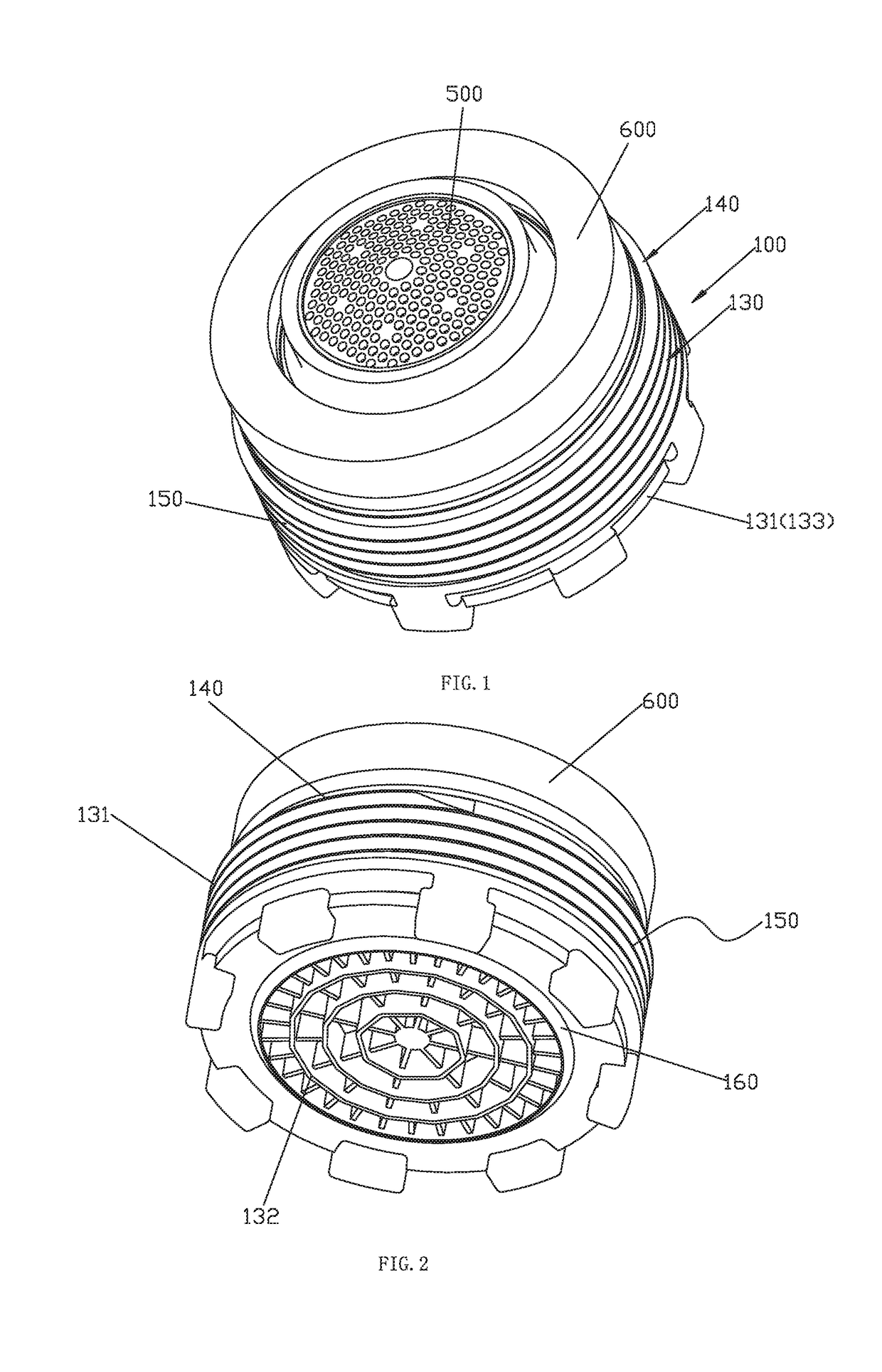
[0042]The housing portion 100 comprises a housing 130 and a fixed ring 140, the housing portion 100 is configured with a mutation cavity 110.

[0043]The housing 130 comprises an outer wall 131 and an inserting element 132 fixedly connected at the bottom portion of the outer wall 131, the inserting element 132 is a grid outlet mesh. The outer wall 131 is disposed with a plurality of suction passages 120 annularly arranged running through the inside and outside of the outer wall 131. The outer wall 131 is step structural with big end down, the step structure has a step surface, the internal port 121 of the suction passage 120 is located on the...


PUM


Abstract

Disclosed is a concealed flow regulator, which comprises a housing portion and a diversion device, the housing portion is disposed with a mutation cavity and a suction passage, the diversion device is used to divide the water flowing, the divided water enters the mutation cavity and negative pressure generates; the external revolution surface of the housing portion is disposed with external thread, the housing portion is threaded to the water supplying opening via the external thread; the suction passage has an internal port faced to the mutation cavity and an external port at the external revolution surface, the air flowing clearance is connected to the external port, so that air can enter the mutation cavity through the air flowing clearance, the external port and the internal port. It has advantages: the flow regulator can be assembled in the water supplying opening and be concealed.

Description

FIELD OF THE INVENTION[0001]The present invention relates to a concealed flow regulator.BACKGROUND OF THE INVENTION[0002]A setting-in element of sanitary ware is disclosed in Chinese patent database with announcement number CN202298777U, CN202139650U, the setting-in element has a housing, the housing is disposed with thread and a housing side with outlet side of flowing hole, at least an insert element is provided to assembled to the housing. The setting-in element is disposed with a flow regulator of ventilation, the periphery wall of the housing defines at least a ventilation passage at a part area of the double-wall structure formed, the housing side of the ventilation passage which face the outlet side is open and is connected to a ventilation opening leading to the inside of the housing. The sealing portion is disposed at the upper end of the inner side of the housing, it can only realize axial sealing, but can not achieve peripheral sealing.SUMMARY OF THE INVENTION[0003]The pr...

Claims


Application Information

Patent Timeline
IPC IPC(8): B05B7/04B05B1/18
CPCB05B1/18B05B7/0425E03C1/084E03C1/086B05B1/22E03C2001/026B05B15/40
Inventor WU, SHILONGZHAO, GUOSONGCHEN, WENXING
Owner XIAMEN SOLEX HIGH TECH IND CO LTD
Why Eureka
Try Eureka